
Antenna switching method, terminal and compute readable storage medium

An antenna switching and terminal technology, applied in wireless communication, climate sustainability, sustainable communication technology, etc., can solve the problems of antenna performance deterioration, signal attenuation, and high power consumption

Inactive Publication Date: 2017-12-15
NUBIA TECHNOLOGY CO LTD
View PDF7 Cites 27 Cited by
  • Summary
  • Abstract
  • Description
  • Claims
  • Application Information

AI Technical Summary

Problems solved by technology

[0004] The main purpose of the present invention is to propose an antenna switching method, a terminal and a computer-readable storage medium, aiming to solve the problem of antenna performance deterioration, signal attenuation, and high power consumption caused by the shielded antenna in the prior art, which affects the user's main equipment. The problem of call throughput rate and data service throughput rate

Method used


Image

  • Antenna switching method, terminal and compute readable storage medium
  • Antenna switching method, terminal and compute readable storage medium
  • Antenna switching method, terminal and compute readable storage medium

Examples


no. 1 example

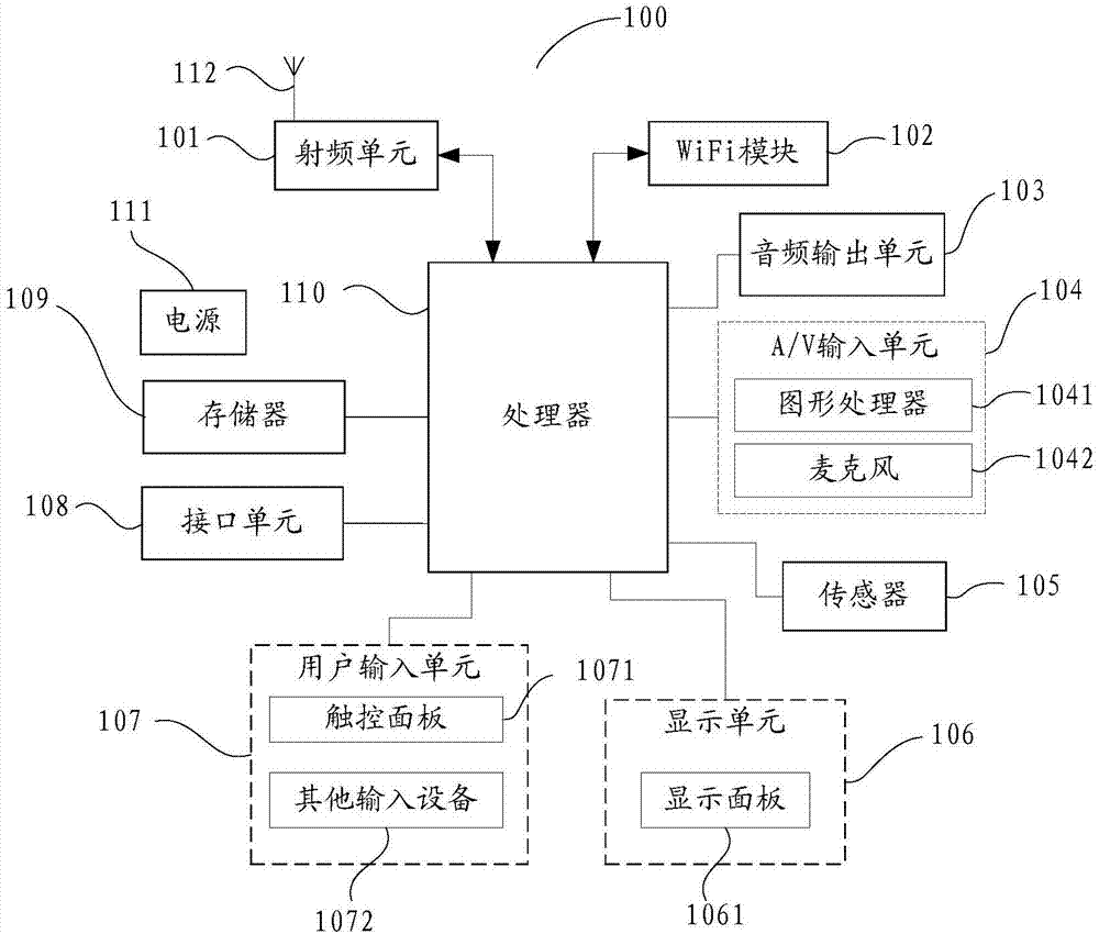
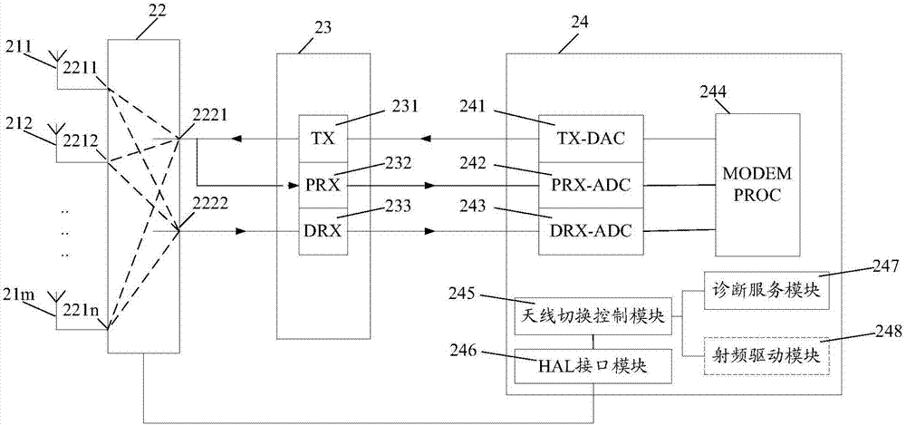
[0053] In order to solve the problems of antenna performance deterioration, signal attenuation, high power consumption, and affecting the user's call throughput rate and data service throughput rate caused by the shielded antenna of the terminal in the prior art, this embodiment will provide an antenna switching method, the antenna switching method is mainly applied to terminals including at least three antennas, in order to facilitate the understanding of the application scenarios of the antenna switching method, see figure 2 , figure 2 A schematic diagram of the hardware structure of a radio frequency unit of a terminal provided in this embodiment, combined with the following figure 2 The hardware structure of the radio frequency unit of the terminal in this embodiment is introduced:

[0054] The terminal in this embodiment includes at least three sets of antennas 211, 212...21m, an antenna gating circuit 22, a radio frequency circuit 23 and a baseband processor 24, and ...

no. 2 example

[0093] see Figure 4 , the terminal has three sets of antennas A, B, and C. Antenna A is set on the top of the back of the terminal, antenna B is set on the lower left of the back of the terminal, and antenna C is set on the lower right of the back of the terminal; the current working antennas are A and B antennas , Antenna A is the main antenna, Antenna B is the auxiliary antenna, Antenna C is the idle antenna, and the communication performance parameter is the uplink transmission power; the diagnostic service module or RF driver module of the terminal collects the data of Antenna A when it is in the working state every 40 milliseconds The uplink transmission power and the uplink transmission power of the B antenna; the antenna switching control module of the terminal obtains the uplink transmission power of the main antenna and the uplink transmission power of the auxiliary antenna collected by the diagnosis service module or the radio frequency driver module at an interval o...

no. 3 example

[0102] This embodiment provides a terminal, see Figure 6 , Figure 6 A schematic diagram of a terminal provided in this embodiment, the terminal includes a processor 601, a memory 602, a communication bus 603, a communication unit 604, and an antenna 605, wherein:

[0103] The communication bus 603 is used to realize connection and communication between the processor 601 and the memory 602;

[0104] The communication unit 604 may be a radio frequency communication unit (radio frequency circuit), or other types of communication units, which include a main transceiver path and an auxiliary receiving path (not shown in the path diagram), and the antenna 605 includes at least three groups, and the at least three Among the antennas in the group, the main antenna that is currently connected to the above-mentioned main transceiver path is the main antenna, the one that is currently connected to the above-mentioned auxiliary receiving path is the auxiliary antenna, and the rest are ...


PUM


Abstract

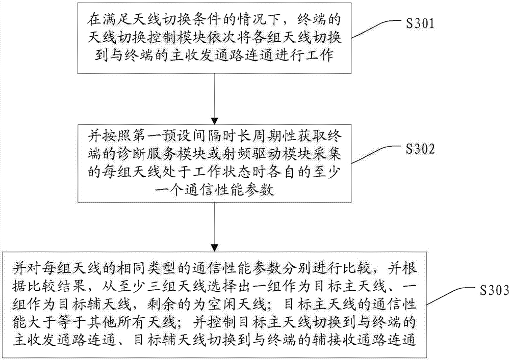
The invention provides an antenna switching method, a terminal and a computer readable storage medium. The antenna switching method is applied to the terminal with at least three groups of antennas; when an antenna switching condition is satisfied, an antenna switching control module at the terminal periodically acquires at least one communication performance parameter of each group of antenna in communication with a main transceiving access, wherein at least one communication parameter is acquired by a diagnosis service module or a radio frequency driving module; the communication performance parameters at the same type of various groups of antennas are respectively compared; a target main antenna and a target auxiliary antenna are selected from at least three groups of antennas according to a comparison result, and the residual antenna is the idle antenna; the communication performance of the target main antenna is greater than and equal to other all antennas; the target main antenna is controlled to switch to communicate with the main transceiving access of the terminal, and the target auxiliary antenna is controlled to switch to communicate with an auxiliary receiving access; when the performance of the antenna in working is deteriorated, two groups of antennas with good communication performance are reselected as the main antenna and the auxiliary antenna to participate in the work; the terminal power consumption is lowered, and the user experience is promoted.

Description

technical field [0001] The present invention relates to the technical field of terminals, and more specifically, to an antenna switching method, a terminal, and a computer-readable storage medium. Background technique [0002] At present, terminals such as smartphones and tablet computers are equipped with two sets of antennas, which are respectively set on the top and bottom areas of the terminal in the vertical screen state. Antenna to assist the main antenna to receive signals. [0003] In actual use, the antenna may be blocked due to the user's grip and other reasons, resulting in deterioration of antenna performance, signal attenuation, and high power consumption, affecting the user's calling and calling rate and data service throughput, and user experience. Low. Contents of the invention [0004] The main purpose of the present invention is to propose an antenna switching method, a terminal and a computer-readable storage medium, aiming to solve the problem of ante...

Claims


Application Information

Patent Timeline
IPC IPC(8): H04B1/401H04W24/02H04W52/02
CPCH04B1/401H04W24/02H04W52/028Y02D30/70
Inventor 郭晓
Owner NUBIA TECHNOLOGY CO LTD
Learn More