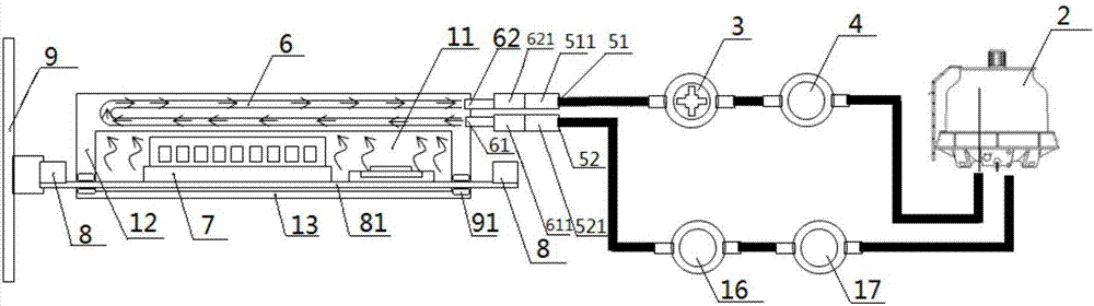
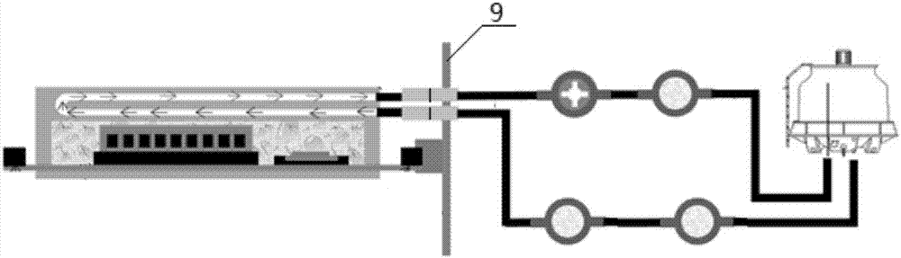
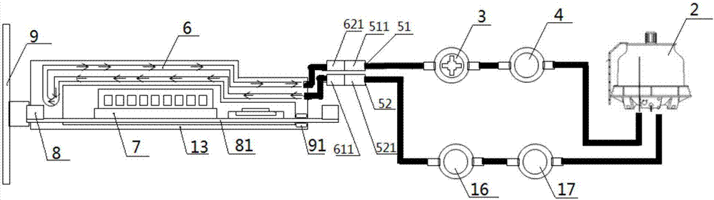
[0031] figure 1 It is a schematic diagram of a longitudinal section structure of a liquid cooling device provided in this application. like figure 1 As shown, the liquid cooling device includes a housing and an external cooling device 2 . Figure 4 Further shows the exploded structure of the shell, as Figure 4 As shown, the shell includes a hollow shell body 12 , a bottom plate 13 and a top plate 14 , the three are sealed and connected to form a closed cavity 11 , and a flow channel 6 is opened on the body of the top plate 14 .
[0032] The casing includes a closed cavity 11, and electronic components 7 to be dissipated are installed in the closed cavity 11. The first cooling liquid is filled in the airtight cavity 11 , is filled with the airtight cavity 11 , and is in direct contact with the electronic components 7 to be dissipated. exist figure 1 In the shown liquid cooling device, the flow channel 6 is not connected to the closed cavity 11 , but is connected to the external cooling device, and the circuit formed by the flow channel 6 and the external cooling device 2 is filled with the second cooling liquid. The external refrigeration device 2 is used to cool the second cooling liquid and provide circulation power for the second cooling liquid. For example, the second cooling liquid carrying heat flows into the external refrigeration equipment, and after being cooled by the external refrigeration equipment, the low-temperature second cooling liquid flows out, and through heat exchange with the first cooling liquid encapsulated inside the casing, the electronic components to be dissipated To dissipate heat. The external refrigeration equipment may be a cold well equipped with power equipment, a cooling tower, and the like. The "body" mentioned in this application refers to the tangible entity itself that constitutes the component, for example, the body of the top plate refers to the plate itself that constitutes the top plate.
[0033] Optionally, an independent power device 3 may also be communicated in the circuit formed by the housing and the external refrigeration device 2, for providing circulating power for the second cooling liquid, so as to increase the rate of circulation of the second cooling liquid in the circuit, Thereby improving heat exchange efficiency.
[0034]Optionally, a purification device 4 , a flow rate monitoring device 16 and a pressure monitoring device 17 may also be communicated in the circuit formed by the casing and the external refrigeration device 2 . Wherein, the power equipment 3 is used to provide circulation power for the second cooling liquid, so that the second cooling liquid continuously circulates between the casing and the external refrigeration equipment 2 , such as a circulation pump, a booster pump and the like. The purification equipment 4 is used to purify the second cooling liquid, remove the mechanical impurities that may exist in the second cooling liquid or the impurities such as microorganisms produced by the second cooling liquid, and prevent the impurities in the second cooling liquid from causing damage to other equipment in the circuit. Purification equipment 4 such as filter membrane, pipeline filter, etc. The flow rate monitoring device 16 is used to monitor the flow rate of the second coolant, and the flow rate monitoring device is such as a flow meter or the like. The pressure monitoring device is used to monitor the pressure of the second coolant, such as a hydraulic gauge or the like.
[0035] It is worth noting that one housing can be connected with one or more external cooling devices. Similarly, an external refrigerating device can only refrigerate one shell, or can cool multiple shells at the same time, and the multiple shells can be connected in series or in parallel. In the following description of the application, The case is described by taking the connection of the housing with an external cooling device as an example.
[0036] The first cooling liquid can be selected from at least one of silicon mineral oil or fluorinated liquid, for example, OptiCool87252UV produced by Liquid CoolSolution Company, or Novec produced by 3M Company TM 649.
[0037] The second cooling liquid may be selected from at least one of water or a combination of additives and water. The additive is a substance that can be dissolved in water or miscible with water, such as ethylene glycol, etc. The condensation point of the composition formed by ethylene glycol and water is lower than -20 ° C. Therefore, under the same conditions, this low condensation The second cooling liquid at the point can exchange more heat with the first cooling liquid. In addition, adding ethylene glycol to the water can effectively inhibit the growth of microorganisms in the water, thus facilitating equipment maintenance and maintenance. In the following description of the present application, further detailed description will be made by taking the second cooling liquid as an example composed of an additive and water.
[0038] The working principle of the submerged liquid cooling device in this embodiment is as follows: after the electronic components to be dissipated run and generate heat, the first coolant filled around it absorbs the heat emitted by the electronic components to be dissipated, and passes through the first The cooling liquid is conducted to the surface of the closed cavity, and then conducted to the external refrigeration equipment through the second cooling liquid flowing in the flow channel, so as to realize the continuous heat dissipation of the electronic components to be dissipated, and the external refrigeration equipment circulates in the process of the second cooling liquid Provide circulation power for the second coolant.
[0039] Next, how the submerged liquid cooling device provided by the present application realizes the heat dissipation of electronic devices will be further described with reference to the accompanying drawings.
[0040] figure 1 The housing shown is made of a thermally conductive material, such as a metal housing or a ceramic housing. Compared with the ceramic shell, the metal shell is easier to shell thickness and has a lower density. When the temperature difference between the two sides is large, the shell can also maintain a stable physical structure without destructive deformation such as fragmentation. use and maintenance of electronic equipment.
[0041] Among them, the structure of the shell can adopt any one of the following structures:
[0042] Structure 1: The top plate, the bottom plate and the main body of the shell can be disassembled.
[0043] Figure 4 It is a structural schematic diagram of a housing provided in this application. As shown in the figure, the housing includes a hollow shell main body 12, a bottom plate 13 sealingly connected with the bottom end of the shell main body 12 and a top plate 14 sealingly connected with the top end of the shell main body 12, the bottom plate 13 and the top plate 14 are detachable from the shell main body 12 connected so that the device single board 81 is installed in the sealed casing, so that the inside of the casing forms a sealed cavity 11 . A flow channel 6 is opened in the body of the top plate 14 . The bottom plate 13 is a flat plate, so that the housing can be stably installed in the complete machine. In addition, in the structure of the housing described above, a seal 91 is provided at the connection between the housing main body 12 and the detachably connected top plate 14 and bottom plate 13 to prevent the first cooling liquid inside the sealed cavity 11 from leaking out of the housing, Specifically, such as figure 1 As shown, the sealing member 91 can be any kind of parts used for sealing, such as sealing rings, sealing strips and the like.
[0044] The equipment single board 81 can be clipped between the shell body 12 and the bottom plate 13 , that is, the top plate 14 , the shell body 12 , the equipment single board 81 and the bottom plate 13 are stacked in sequence.
[0045] Optionally, the device single board 81 may also be clamped between the top board 14 and the shell body 12 , that is, the top board 14 , the device single board 81 , the shell body 12 and the bottom board 13 are sequentially stacked.
[0046] Optionally, the bottom plate 13 and the shell main body 12 are fastened and connected by fasteners, such as screws, or fixedly connected by buckles.
[0047] Structure 2: The bottom plate and the shell body are detachable, and the top plate and the shell body are not detachable.
[0048] Figure 4a A structural schematic diagram of another housing provided by the present application, and Figure 4 The difference is that the top plate 14 and the shell main body 12 are integrally formed, and only the bottom plate and the shell main body are detachable, thereby increasing the airtightness of the airtight cavity 11.
[0049] In this manner, the equipment single board 81 is clamped between the shell body 12 and the bottom plate 13 , that is, the top plate 14 , the shell body 12 , the equipment single board 81 and the bottom plate 13 are sequentially stacked.
[0050] Structure 3, the top plate and the main body of the shell are detachable, and the bottom plate and the main body of the shell are not detachable ( Figure 4 and Figure 4a not shown).
[0051] and Figure 4a The structure 2 shown is similar, the bottom plate 13 and the shell body 12 are integrally formed, and only the top plate and the shell body are detachable, which increases the airtightness of the airtight cavity 1 .
[0052] In the third structure, the equipment board 81 is sandwiched between the top board 14 and the shell body 12 , that is, the top board 14 , the equipment board 81 , the shell body 12 and the bottom board 13 are stacked in sequence.
[0053] Further, as figure 1 In the shown liquid cooling device, at least one electronic component 7 to be dissipated is included in the airtight cavity 11 of the casing. The electronic components to be dissipated include CPU, memory or network card, etc., and the electronic components 7 to be dissipated are installed on a printed circuit board (printed circuit board, PCB board) according to a preset position and connection mode to form a device single board 81 . The equipment board 81 is fixed in the airtight cavity 11 . In addition, the electronic components to be dissipated in the electronic equipment may be the same or different, which is not limited in this application. like figure 1 As shown, the electronic device includes two different electronic components.
[0054] A connector 8 is also installed on the device single board 81 , and the connector 8 is used for electrical connection with the backplane 9 or other electronic components. Wherein, the number of connectors 8 on the device single board 81 may be one or more. The connector 8 can be arranged outside the housing, or can be snap-fitted on the housing body. E.g, figure 1 Two connectors 8 are installed on the device single board 81 shown, and the connectors 8 are arranged outside the casing. The backplane 9 is a circuit board, which is used for electrical connection between the electronic components 7 to be dissipated and other electronic components, wherein the other electronic components are electronic components arranged outside the casing.
[0055] Optionally, figure 2 It is a schematic diagram of the longitudinal section structure of another submerged liquid cooling device provided in this application. and figure 1 The difference is that figure 2 The connector on the right side of the equipment single board 81 in the shown immersion liquid cooling device is electrically connected to other electronic components. Wherein, the channel for connecting the housing to the external cooling device 2 may or may not pass through the backplane 9 according to business requirements, which is not limited in this application.
[0056] For example, as figure 2 As shown, the connection channel between the housing and the external cooling device 2 passes through the back plate 9 .
[0057] Furthermore, in combination with the different shapes of the electronic components to be dissipated, the shape of the housing in the submerged liquid cooling device provided by the present application may also change accordingly.
[0058] The shape of the shell can be as figure 1 Shown is a cuboid structure. see also image 3 , the shape of the housing matches the shape of the electronic components 7 to be dissipated. Since a plurality of different electronic components 2 are arranged on the equipment single board 81, the physical shapes of these electronic components are not the same, and their heights are quite different. Changes, such as the shape of the housing changes with the height of the electronic components. On the one hand, the volume of the whole machine is reduced, and on the other hand, the volume of the inner cavity of the housing is reduced, thereby reducing the amount of the first cooling liquid, thereby reducing the cooling cost. Correspondingly, the top plate 14 may be a flat plate or a curved plate, which is adapted to the shape of the casing to form the airtight cavity 11 .
[0059] It is worth noting that, for the same electronic device, one housing can be provided for each electronic component to be dissipated, or one housing can be provided for two or more electronic components to be dissipated.
[0060] At least one flow channel 6 can be opened on each shell body, and each flow channel communicates with the external refrigeration device 2 .
[0061] specifically, Figure 5 A cross-sectional top view of a runner top plate provided for this application, such as Figure 5 As shown, a linear flow channel 6 is opened on the body of the top plate 14 . The linear flow channel 6 has small flow resistance to the second cooling liquid, so the second cooling liquid has a fast flow speed and high heat exchange efficiency, and the linear flow channel is easy to open.
[0062] Image 6 A cross-sectional top view of the flow channel top plate provided for this application, such as Image 6 As shown, two curved flow channels 6 are opened on the body of the top plate 14 . The two flow channels 6 communicate with the same external cooling device 2 in parallel, so that the second cooling liquid in each flow channel 6 discharges the heat conducted by the first cooling liquid to the outside of the electronic device, thereby improving heat dissipation efficiency.
[0063] When the power consumption of the electronic components is small and the demand for heat dissipation is low, the plurality of flow channels may be connected to reduce the number of closed loops and facilitate cooling of the second cooling liquid. When the power consumption of electronic components is large and the demand for heat dissipation is high, the multiple flow channels can be disconnected to form multiple closed loops for the second coolant circulation, that is, multiple paths are directed to The liquid cooling device provides a low-temperature second cooling liquid, so as to improve heat dissipation efficiency.
[0064] As a possible implementation, in the present application, the flow channel 6 is opened inside the housing body, that is, it may be opened inside at least one of the main body 12 , the top plate 14 or the bottom plate 13 .
[0065] Specifically, such as figure 1 As shown, the flow channel 6 is opened in the body of the top plate 14, so that the heated first cooling liquid is cooled on the top of the casing, and the cooled first cooling liquid naturally descends, thereby forming a heat sink inside the casing. Convection, and then continue to dissipate heat from the electronic components.
[0066] image 3 It is a schematic diagram of the longitudinal section structure of another submerged liquid cooling device provided in this application. see image 3 ,and figure 1The difference is that flow passages 6 are respectively provided in the body of the top plate 14 and the main body of the shell body 12, and the two flow passages are connected, that is, the two flow passages 6 are connected in series and communicate with the same external refrigeration device 2 to form a The closed loop circulating the second cooling liquid increases the heat exchange area between the first cooling liquid and the second cooling liquid, thereby improving heat dissipation efficiency.
[0067] Optionally, flow passages 6 are provided in the body of the top plate 14 and the body of the shell main body 12 respectively. The two flow passages are not communicated, and are connected in parallel with the refrigeration equipment 5 to form two closed loops circulating the second cooling liquid. The rising first coolant is cooled on the top of the shell, and the cooled first coolant naturally descends, thereby forming heat convection inside the shell, and the low-temperature second coolant passes through the shell body The flow channel on 12 further cools the descending first coolant, on the one hand, speeds up the heat convection cycle, and on the other hand, makes the first coolant cool down more fully, thereby improving the heat dissipation efficiency of the electronic components 2 .
[0068] The shape of the flow channel 6 can be linear distribution, curved distribution or spiral distribution. Wherein, the curved distribution means that there is at least one bend in the flow channel 6, such as serpentine distribution, zigzag distribution, U-shaped distribution, etc., and the spiral distribution means that the flow channel extends helically.
[0069] For example, as Figure 5 As shown, the linear distribution means that the flow channel 6 is linear, that is, there is a linear channel between the housing liquid inlet 61 and the housing liquid outlet 62 .
[0070] For the case that the casing includes multiple flow channels 6 , different flow channels 6 can be divided into main flow channels and branch flow channels. The split channel is connected with the main channel, the main channel includes the main channel for the liquid inlet and the optional main channel for the liquid outlet. The flow channel that directly communicates with the external refrigeration equipment 2 without converging after the main flow channel is branched.
[0071] specifically, Figure 8 A schematic diagram of the three-dimensional structure of the roof that can realize the main flow channel and the flow distribution channel provided by the application, such as Figure 8 As shown, the flow channel 6 includes a linear main liquid inlet channel 63, a linear main liquid outlet channel 64 and a plurality of U-shaped sub-flow channels 65, and the ports of the main liquid inlet channel 63 and the main liquid outlet channel 64 are opened respectively. On the surface of the top plate 14, it communicates with the outside world. The second cooling liquid flows into the top plate 14 through the liquid inlet main channel 63 arranged on the lower layer, and flows out of the top plate 14 through the main channel 64 of the liquid outlet 14 arranged on the upper layer after passing through the branch flow channel 65. Circulation to external refrigeration unit 2.
[0072] see figure 1 , the two ports of the channel 6 on the housing body are the housing liquid inlet 61 and the housing liquid outlet 62, which are respectively used for the second cooling liquid to flow into the channel 6 and out of the channel 6, so that the second cooling liquid The liquid circulates between the flow channel 6 and the external refrigeration equipment 5 .
[0073] Optionally, as in figure 1 As shown, the housing liquid inlet 61 and the housing liquid outlet 62 are arranged adjacent to each other, which facilitates the communication between the flow channel 6 and the refrigeration device 5 and reduces space occupation.
[0074] see figure 1 , the housing liquid inlet 61 is provided with a housing liquid inlet quick joint 611, when the quick joint is used alone, it can stop the liquid in the pipeline from flowing out, after the two quick joints are connected, the pipeline forms a passage, and the liquid It can flow in the formed passage, and after the two butted quick connectors are separated, the pipeline can be sealed immediately to stop the liquid in the pipeline from flowing out.
[0075] like figure 1 As shown, the housing liquid outlet 62 is provided with a housing liquid outlet quick connector 621, and the cooling liquid inlet 51 is provided with a cooling liquid inlet quick connector 511 matching the housing liquid outlet quick connector 621, A cooling liquid outlet quick joint 521 matching the shell liquid inlet quick joint 611 is provided on the cooling liquid outlet 52 .
[0076] Optionally, the housing liquid inlet quick connector 611 is in fixed communication with the corresponding cooling liquid outlet quick connector 521 , and the cooling liquid inlet quick connector 511 is in fixed communication with the corresponding housing liquid outlet quick connector 621 .
[0077] The flow passage 6 communicates with the refrigeration liquid outlet 52 through the casing liquid inlet 61 , and the casing liquid outlet 62 communicates with the refrigeration liquid inlet 51 , so that the flow passage 6 and the refrigeration device 5 form a closed circuit.
[0078] Optionally, as in figure 1 As shown, the second cooling liquid flows into the flow channel 6 from an end close to the electronic component 7 to be dissipated, and flows out of the flow channel 6 from an end far away from the electronic component 7 to be dissipated, so that the low-temperature second cooling liquid First of all, it contacts the high-temperature housing and performs heat exchange with it, thereby improving the heat dissipation efficiency of the electronic components to be dissipated.
[0079] Through the description of the above content, the liquid cooling device provided by this application encapsulates the electronic components to be dissipated in a metal sealed casing filled with the first cooling liquid, and an external cooling device is opened on the body of the sealed casing The flow channel through which the equipment communicates is filled with the second cooling liquid used to circulate between the sealed housing body and the external cooling equipment. The heat generated by the electronic components during operation is directly transferred to the first cooling liquid, and the first cooling liquid The liquid then transfers heat to the low-temperature second cooling liquid through the metal sealed casing to complete the heat exchange between the electronic components and the outside world. The first cooling liquid directly in contact with the electronic components in the sealed casing uses a small amount, and each The sealed shells are independent of each other, which facilitates the maintenance of electronic components and improves the maintenance efficiency. On the other hand, since the second cooling liquid circulating between the closed cavity and the external cooling equipment can use cheap water or other cheap cooling media, it solves the problem that the full immersion or nodal liquid cooling needs to consume a large amount of expensive cooling liquid , reducing the cost of the liquid cooling system. Moreover, through the design of the position and quantity of the flow channels, the heat dissipation efficiency of the liquid cooling system is improved.
[0080] Combination of the above Figure 1 to Figure 8 The structure of the liquid cooling device provided by this application is introduced in detail. Next, in combination with Figure 9 and Figure 10 The blade server and the rack server applying the liquid cooling device in this application are further introduced.
[0081] Figure 9 A schematic diagram of the structure of a liquid-cooled blade server provided by this application, as shown in the figure, the blade server includes 4 blade servers, each blade server is installed in a housing, and the 4 housings The body shares an external refrigeration equipment to form a set of above-mentioned immersion cooling liquid device. Wherein, a plurality of blade servers are connected through a backplane 9 . The structure of the immersion cooling device and Figure 1 to Figure 8 The structures are the same, and will not be repeated here.
[0082] Figure 10 It is a schematic structural diagram of a realizable liquid-cooled rack-mounted server group provided by the present application. As shown in the figure, the rack-mounted server group includes four rack-mounted servers C. Wherein, each rack-mounted server is respectively installed in a casing, and the four casings share one external cooling device to form the above-mentioned submerged liquid cooling device. In this mode, only Provide power equipment and purification equipment, but do not install flow rate monitoring equipment or pressure monitoring equipment. Among them, the structure of the immersion cooling device is the same as Figure 1 to Figure 8 The structures are the same, and will not be repeated here.
[0083] It is worth noting that, in Figure 9 server blade shown and Figure 10 In the rack server shown, different electronic devices can realize the cooling of the second cooling liquid through the same external cooling device, so as to transfer the heat generated by the first cooling liquid to the outside of the blade server/rack server. Different electronic devices can also realize the cooling of the second coolant through multiple external cooling devices, so as to improve the heat dissipation efficiency of the blade server/rack server.
[0084] The present application has been described in detail above in conjunction with specific implementations and illustrative examples, but these descriptions should not be construed as limiting the present application. Those skilled in the art understand that without departing from the spirit and scope of the present application, various equivalent replacements, modifications or improvements can be made to the technical solutions and implementations of the present application, all of which fall within the scope of the present application. The scope of protection of the present application is subject to the appended claims.