Turret positioning device of numerical control turret

A technology of positioning device and numerical control turret, which is applied in the direction of stripping device, metal processing equipment, forming tools, etc., can solve the problems of increasing the machining accuracy of parts, high coaxiality, and wear of parts, so as to reduce damage to parts and improve assembly efficiency , Increase the effect of lubricity

Inactive Publication Date: 2017-12-19
张家港市丰乐汽车设备有限公司
View PDF5 Cites 1 Cited by
  • Summary
  • Abstract
  • Description
  • Claims
  • Application Information

AI Technical Summary

Problems solved by technology

However, during the assembly process, because the positioning pin seats 2 and 8 are fixed on the fuselage, workers can only install other components on the positioning pin seats in sequence during assembly, and can only work beside the fuselage, which is time-consuming and laborious.
In addition, the positioning pin 4 in the traditional turret positioning device achieves the purpose of reducing the radial force of the cylinder shaft through the floating joint 5 and the cylinder 6. The floating joint 5 is installed in the connecting seat 7, so the positioning pin 4, the pin sleeve 3, and the floating joint 5. The connecting seat 7 and the cylinder shaft need a high coaxiality to increase the machining accuracy of the parts, and this connection method is not effective in reducing the radial force
At the same time, there is no lubricating device in the turret positioning device, and the frequent insertion and insertion of the positioning pin 4 will cause friction with the pin sleeve 3, resulting in component wear and friction. The frictional heat generated by the friction will easily cause thermal deformation of the positioning pin and the pin sleeve, which may cause the positioning pin Locked with the pin sleeve, not working properly
So this system is unreasonable and needs improvement

Method used


Image

  • Turret positioning device of numerical control turret
  • Turret positioning device of numerical control turret
  • Turret positioning device of numerical control turret

Examples


Embodiment Construction

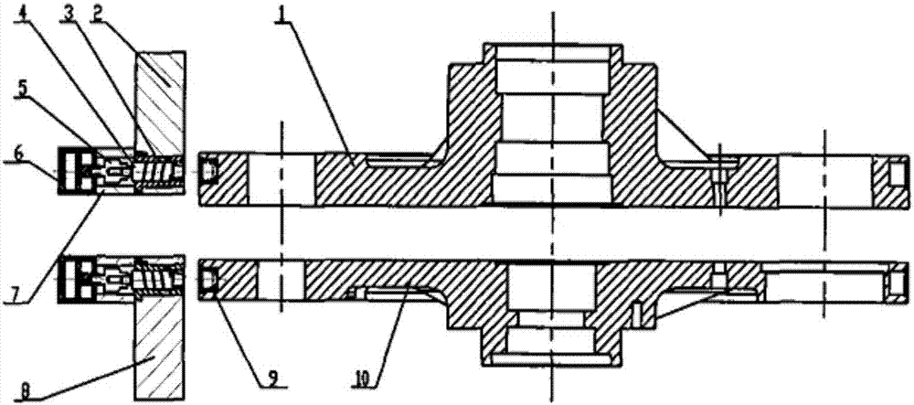
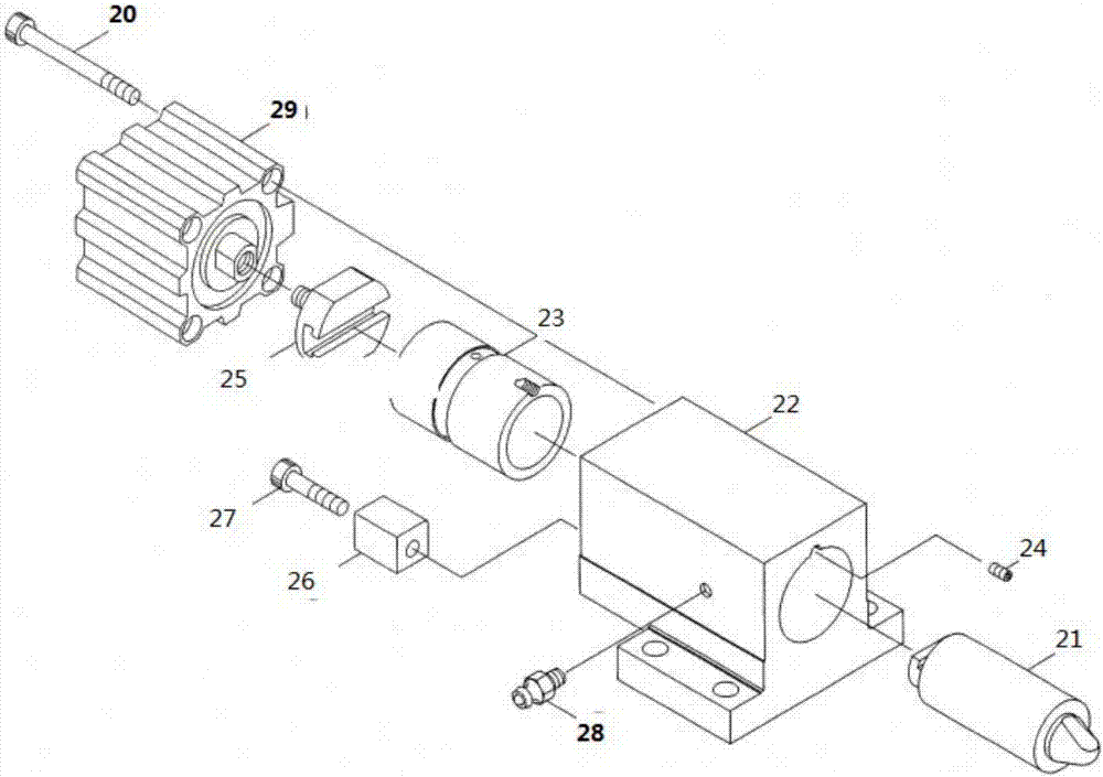
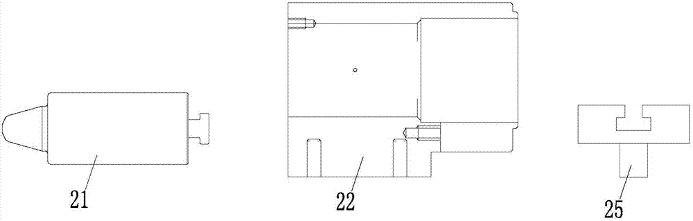
[0020] The turret positioning device of this embodiment includes a mounting block, a cylinder and a positioning pin. The mounting block has a cavity connected at both ends, the positioning pin is arranged in the cavity, and the cylinder is mounted in the cavity of the mounting block. One end of the body, the cylinder is connected with the positioning pin and can drive the positioning pin to move in the direction of cavity extension. A connector is installed between the cylinder and the positioning pin, one end of the connector is fixed to the cylinder through threads, the other end is provided with a T-shaped notch, and the end of the positioning pin is matched with a T-shaped connector. At the same time, a guide key is added to be parallel to the plane on the connector to play a guiding role and completely eliminate the generation of radial force. In addition, the installation block of the new turret positioning device is equipped with an oil nozzle, and there are correspondi...


PUM


Abstract

This invention discloses a turret positioning device of a numerical control turret. The turret positioning device comprises a mounting block, an air cylinder and a positioning pin, wherein the mounting block is provided with a cavity body with two ends communicated, the positioning pin is arranged in the cavity body, and the air cylinder is mounted at one end of the cavity body of the mounting block; the air cylinder is connected with the positioning pin and can drive the positioning pin to move in the extension direction of the cavity body; a connecting joint is mounted between the air cylinder and the positioning pin, and one end of the connecting joint is fixed to the air cylinder through threads, and a T-shaped notch is formed in the other end of the connecting joint; a T-shaped connecting joint is arranged at the tail end of the positioning pin in a matched mode; a guiding key parallel to the connecting joint is mounted below the connecting joint to eliminate the radial force of a air cylinder shaft; an oil nozzle is mounted on the mounting block, and an annular notch and an oil passing hole are processed in a turning mode in the corresponding positions of the inner wall and the outer wall of a pin sleeve, and lubricating oil can be periodically added between the pin sleeve and the positioning pin, component damaging caused by friction is reduced, meanwhile the fact that the positioning pin is out of action caused by locking due to heat expansion of the positioning pin and the pin sleeve due to overheating friction is prevented.

Description

technical field [0001] The present application relates to a numerically controlled turret device, in particular to a turret positioning device for a numerically controlled turret. Background technique [0002] The turret structure of the CNC punching machine generally includes two upper and lower turntables, and the upper and lower turntables have the same rotation axis. The upper and lower molds of the stamping die are respectively installed on the upper and lower trays. During stamping, the concentricity of the upper and lower molds is highly required. Therefore, the synchronization requirements for the upper and lower turntables are very high. The upper and lower turntables may have a small amount of radial direction during long-term use. This gap will cause errors in machining accuracy and damage to the mold, so precise positioning is required for loading. [0003] ginseng figure 1 As shown, the traditional turret positioning device pushes and pulls the positioning pin...

Claims


Application Information

Patent Timeline
Patent Type & Authority Applications(China)
IPC IPC(8): B21D37/06B21D45/00
CPCB21D37/06B21D45/003
Inventor 赵英
Owner 张家港市丰乐汽车设备有限公司
Why Eureka
Try Eureka