Machining method for tapered shaft sleeve

A processing method and technology of tapered shafts, which are applied in metal processing equipment, manufacturing tools, grinding machine parts, etc., can solve problems such as affecting the health of operators, and achieve the advantages of reducing scrap rate, simple process and reducing production costs. Effect

Active Publication Date: 2017-12-19
CHONGQING SUTENG MACHINERY MFG
View PDF8 Cites 4 Cited by
  • Summary
  • Abstract
  • Description
  • Claims
  • Application Information

AI Technical Summary

Problems solved by technology

[0012] The purpose of the present invention is to provide a processing method of a tapered bushing to solve the problem in the prior art that metal grinding floats in the air and affects the health of operators

Method used


Image

  • Machining method for tapered shaft sleeve
  • Machining method for tapered shaft sleeve
  • Machining method for tapered shaft sleeve

Examples


Embodiment

[0037] Embodiment: A processing method of a tapered bushing in this scheme includes the following steps: (1) cutting the wire blank into several sections of bar blanks;

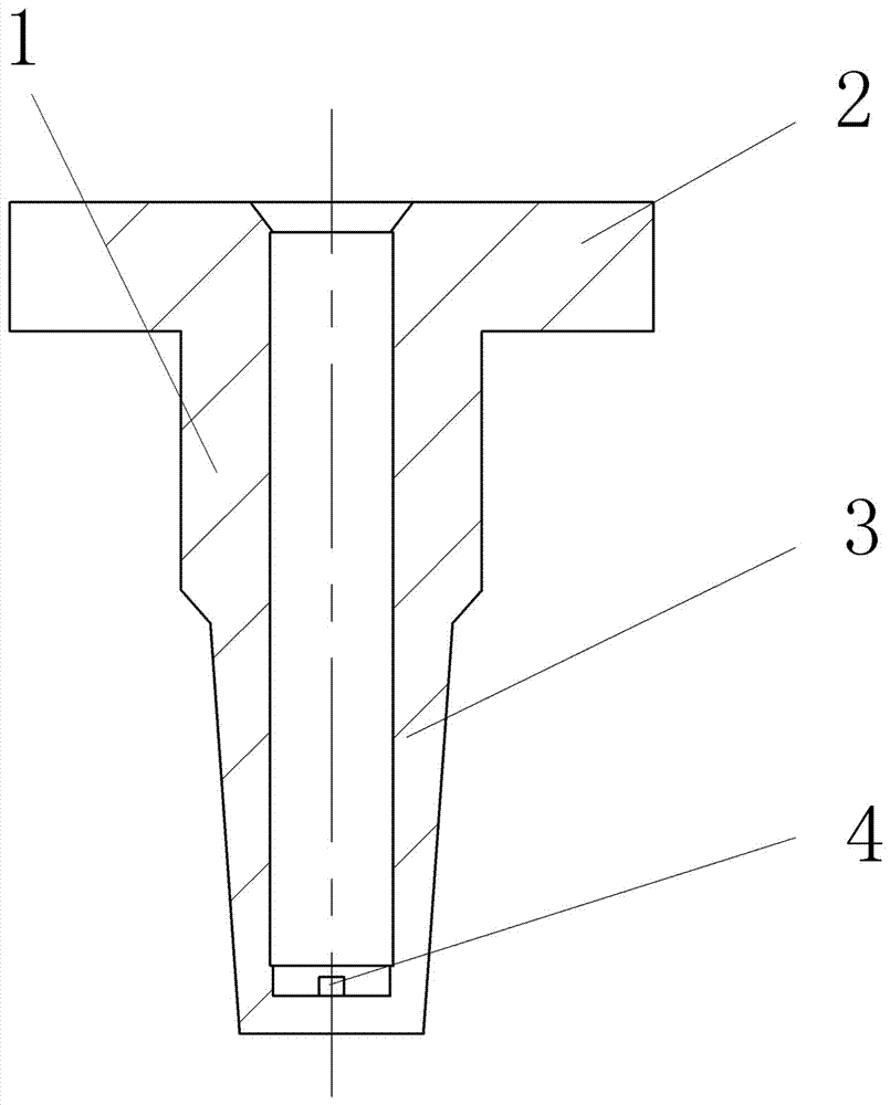
[0038] (2) if figure 1 As shown, one end of the rod blank is upset, and the other end is stretched to expand the diameter. The upsetting part on the rod blank forms the third rod body blank 2, and the reduced diameter part on the rod body blank forms the first rod body blank 3. A second rod body blank 1 is formed at the part between the upsetting part and the diameter reduction part on the piece blank, and a chamfer is processed between the first rod body blank 3 and the second rod body blank 1, and the outer end of the first rod body blank 3 is also Process a chamfer first;

[0039] (3) Flatten the outer surface of the third rod blank 2 first, and then stretch a round hole on the outer end of the third rod blank 2, and the round hole extends to the intersection position of the second rod blank 1 and the thi...


PUM


Abstract

The invention belongs to the field of shaft sleeve machining and particularly discloses a machining method for a tapered shaft sleeve. The step of collecting and discharging of metal grindings is combined with the step that a blank of a specific workpiece is machined in the prior art, so that the problem that in the prior art, the metal grindings float in air and affects physical health of operators is solved. Used equipment in the scheme comprises a base, a feeding device, a polishing fixing device and a spiral polishing mechanism. Meanwhile, the beneficial effects that an original scheme is simple in process, the rejection rate is greatly decreased, and accordingly the production cost is reduced are achieved.

Description

technical field [0001] The invention belongs to the field of shaft sleeve processing. Background technique [0002] An existing shaft sleeve includes a first rod body, a second rod body, and a third rod body arranged coaxially, the second rod body is located between the first rod body and the third rod body, and the first rod body, the second rod body, and the third rod body The outer diameter of the rod body becomes larger successively, a chamfer is provided between the first rod body and the second rod body, a mounting hole is provided on the outer end surface of the third rod body, and the mounting hole extends into the first rod body, and a circle is provided at the bottom of the mounting hole. Shaped boss, at present, when processing this axle sleeve, its technology is complicated, and the reject rate of the axle sleeve after processing is high. [0003] The patent document whose authorized announcement number is CN105269259B discloses a processing method of a shaft sl...

Claims


Application Information

Patent Timeline
Patent Type & Authority Applications(China)
IPC IPC(8): B24B5/14B24B5/35B24B55/12B24B47/20B24B41/02B24B41/00B23P15/00
CPCB23P15/00B24B5/14B24B5/35B24B41/002B24B41/02B24B47/20B24B55/12
Inventor 王全中
Owner CHONGQING SUTENG MACHINERY MFG
Why Eureka
Try Eureka