Steel backing shot blasting equipment for production of brake pads

A brake pad and steel back technology, which is applied in the field of steel back shot blasting equipment for brake pad production, can solve problems such as low work efficiency, high production cost, and cumbersome operation

Active Publication Date: 2017-12-19
浙江翘楚汽车零部件有限公司
View PDF7 Cites 6 Cited by
  • Summary
  • Abstract
  • Description
  • Claims
  • Application Information

AI Technical Summary

Problems solved by technology

[0006] In order to overcome the shortcomings of the current steel-backed shot blasting equipment, such as high production cost, poor shot blasting effect, cumbersome operation, and low work efficiency, the technical problem to be solved by the present invention is to provide a low production cost, good shot blasting effect, and easy operation. Simple and efficient steel-backed shot blasting equipment for brake pad production

Method used


Image

  • Steel backing shot blasting equipment for production of brake pads
  • Steel backing shot blasting equipment for production of brake pads
  • Steel backing shot blasting equipment for production of brake pads

Examples


Embodiment 1

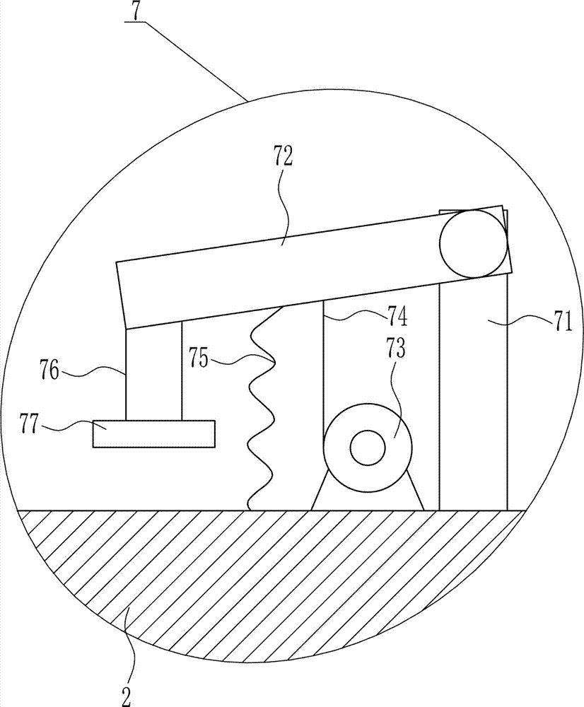
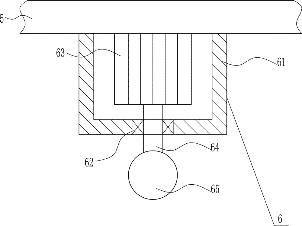
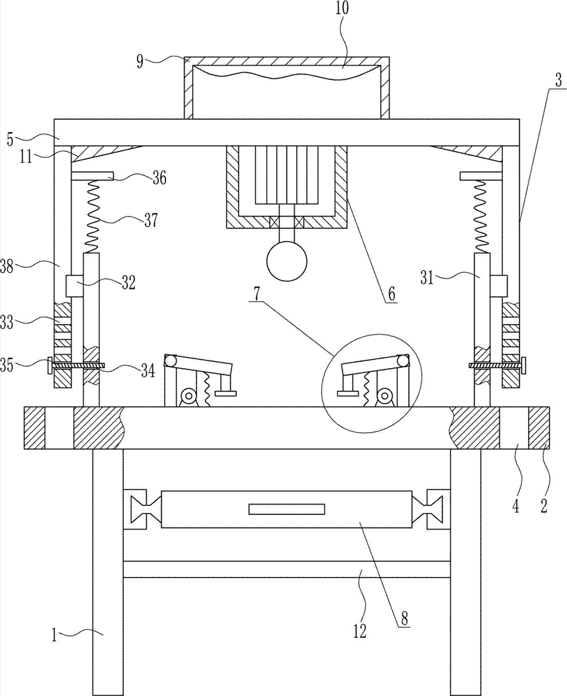
[0036] A kind of steel back shot blasting equipment for brake pad production, such as Figure 1-7 As shown, it includes a leg 1, a horizontal plate 2, a lifting device 3, a top plate 5, a shot blasting device 6 and a cross bar 12. The top of the leg 1 is connected by bolts to install a horizontal plate 2, and the top of the horizontal plate 2 is symmetrical There is a lifting device 3, through-holes 4 are opened at the left and right ends of the horizontal plate 2, and a top plate 5 is connected to the lifting part of the lifting device 3, and the top plate 5 is arranged horizontally. The lower part between the legs 1 is connected with a cross bar 12 by means of bolt connection.

Embodiment 2

[0038] A kind of steel back shot blasting equipment for brake pad production, such as Figure 1-7 As shown, it includes a leg 1, a horizontal plate 2, a lifting device 3, a top plate 5, a shot blasting device 6 and a cross bar 12. The top of the leg 1 is connected by bolts to install a horizontal plate 2, and the top of the horizontal plate 2 is symmetrical There is a lifting device 3, through-holes 4 are opened at the left and right ends of the horizontal plate 2, and a top plate 5 is connected to the lifting part of the lifting device 3, and the top plate 5 is arranged horizontally. The lower part between the legs 1 is connected with a cross bar 12 by means of bolt connection.

[0039] The lifting device 3 includes a fixed seat 31, a first slide block 32, a screw rod 35, a fixed block 36, a first spring 37 and a first slide rail 38, and the top of the horizontal plate 2 is vertically installed with a fixed seat by means of a bolt connection. 31. A first slide block 32 is in...

Embodiment 3

[0041] A kind of steel back shot blasting equipment for brake pad production, such as Figure 1-7 As shown, it includes a leg 1, a horizontal plate 2, a lifting device 3, a top plate 5, a shot blasting device 6 and a cross bar 12. The top of the leg 1 is connected by bolts to install a horizontal plate 2, and the top of the horizontal plate 2 is symmetrical There is a lifting device 3, through-holes 4 are opened at the left and right ends of the horizontal plate 2, and a top plate 5 is connected to the lifting part of the lifting device 3, and the top plate 5 is arranged horizontally. The lower part between the legs 1 is connected with a cross bar 12 by means of bolt connection.

[0042] The lifting device 3 includes a fixed seat 31, a first slide block 32, a screw rod 35, a fixed block 36, a first spring 37 and a first slide rail 38, and the top of the horizontal plate 2 is vertically installed with a fixed seat by means of a bolt connection. 31. A first slide block 32 is in...


PUM


Abstract

The invention belongs to the technical field of brake pad production, and particularly relates to a steel backing shot blasting device for production of brake pads. The steel backing shot blasting device for production of the brake pads has the advantages that the manufacturing cost is low, the shot blasting effect is good, operation is simple, and the working efficiency is high. The steel backing shot blasting device for production of the brake pads comprises supporting legs and the like; a transverse plate is arranged on the tops of the supporting legs through bolts; lifting devices are symmetrically arranged on the left side and the right side of the top of the transverse plate; through holes are formed in the left end and the right end of the transverse plate separately; a top plate is connected to lifting parts of the lifting devices and is horizontally arranged; a shot blasting device is arranged in the middle of the bottom of the top plate; and a cross rod is connected to the lower portion between the two supporting legs through bolts. According to the steel backing shot blasting device for production of the brake pads, the effects of low manufacturing cost, good shot blasting effect, simple operation and high working efficiency can be achieved.

Description

technical field [0001] The invention belongs to the technical field of brake pad production, in particular to a steel-backed shot blasting equipment for brake pad production. Background technique [0002] Brake pads: generally composed of a steel back, an adhesive heat insulation layer and a friction block. The steel back needs to be painted to prevent rust. During the painting process, an SMT-4 furnace temperature tracker is used to detect the temperature distribution during the painting process to ensure quality. . The heat insulation layer is composed of materials that do not conduct heat, and the purpose is heat insulation. The friction block is composed of friction material and adhesive, which is squeezed on the brake disc or brake drum to generate friction during braking, so as to achieve the purpose of vehicle deceleration and braking. Due to friction, the friction block will be gradually worn, generally speaking, the lower the cost of the brake pads, the faster the...

Claims


Application Information

Patent Timeline
Patent Type & Authority Applications(China)
IPC IPC(8): B24C3/04B24C3/32B24C9/00
CPCB24C3/04B24C3/32B24C9/00
Inventor 柯达易荣李满红其他发明人请求不公开姓名
Owner 浙江翘楚汽车零部件有限公司
Why Eureka
Try Eureka