

Engine and engine oil-gas separator
A technology of oil-gas separator and engine, which is applied in the direction of engine components, machines/engines, mechanical equipment, etc., can solve the problems of oil-gas separator separation effect, structure, and cost, etc., so as to improve oil-gas separation efficiency, compact structure, and simple effect
- Summary
- Abstract
- Description
- Claims
- Application Information
AI Technical Summary
Problems solved by technology
Method used
Image

Examples
Embodiment Construction
[0029] The embodiment of the invention discloses an engine oil-gas separator, which takes into account the separation effect, structure and cost of the oil-gas separator.
[0030] The following will clearly and completely describe the technical solutions in the embodiments of the present invention with reference to the accompanying drawings in the embodiments of the present invention. Obviously, the described embodiments are only some, not all, embodiments of the present invention. Based on the embodiments of the present invention, all other embodiments obtained by persons of ordinary skill in the art without making creative efforts belong to the protection scope of the present invention.
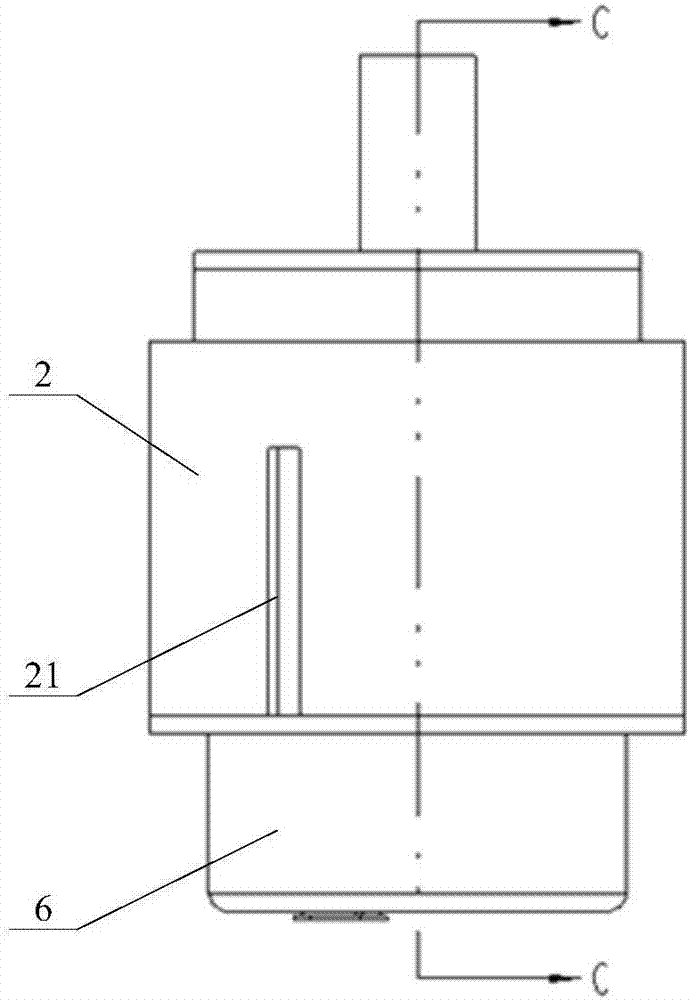
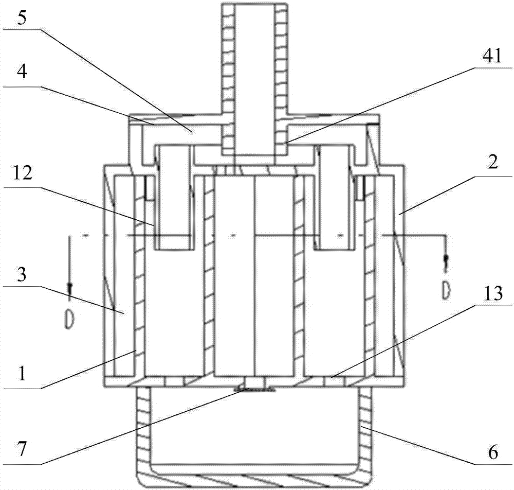
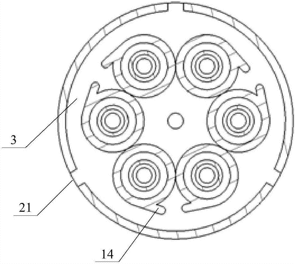
[0031] see Figure 1-Figure 6 , figure 1 A schematic diagram of the external structure of a specific embodiment of the engine oil-gas separator provided by the present invention; figure 2 for figure 1 Schematic diagram of the C-C cross-sectional structure of ; image 3 for figure 2 D...
PUM
 Abstract
Description
Claims
Application Information