Supercharge Your Innovation With Domain-Expert AI Agents!

Automatic exhaust method of electronic unit pump

A technology of automatic exhaust and unit pump, which is applied to engine components, combustion engines, machines/engines, etc., and can solve problems such as time-consuming and cumbersome operation processes

Active Publication Date: 2017-12-19
HEBEI HUABEI DIESEL ENGINE
View PDF6 Cites 0 Cited by
  • Summary
  • Abstract
  • Description
  • Claims
  • Application Information

AI Technical Summary

Problems solved by technology

The entire operation process is cumbersome and time-consuming, and it is necessary to overcome the limitations of the car body structure and operate close to the engine

Method used


Image

  • Automatic exhaust method of electronic unit pump
  • Automatic exhaust method of electronic unit pump

Examples


Embodiment Construction

[0021] Below in conjunction with embodiment the present invention is described in further detail:

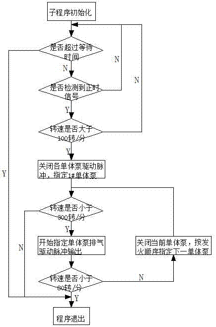
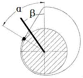
[0022] The electronically controlled unit pump automatic exhaust method, by adding an exhaust subroutine to the existing electronic control system, when the unit pump intake occurs, enter the exhaust subroutine, under the control of the exhaust subroutine The engine moves over 120 rpm under the drag of the starter motor. The starter motor drives the engine flywheel and crankshaft, and then drives the oil supply camshaft through the gear. During the ascending stage, the driving pulse covering the entire ascending stage of the piston is output to the solenoid valve of the unit pump, and the solenoid valve is in the closed state, among which figure 2 As shown, in normal operation, it is only necessary to give the solenoid valve a narrow driving pulse corresponding to the rotation angle β of the oil supply cam in the rising stage. correspond. The unit pump sends the fuel sucked i...


PUM


Abstract

The invention discloses an automatic exhaust method of an electronic unit pump, which belongs to the technical field of diesels. After air enters the unit pump, the unit pump enters an exhaust subprogram, an engine is driven to move by a start motor under the control of the exhaust subprogram, an oil supply cam is driven to rotate by the engine, when a piston is driven to be in an ascending section by the oil supply cam, driving pulse which covers the whole ascending section of the piston is output to an electromagnetic valve of the unit pump, the electromagnetic valve is closed, oil which is sucked into an internal oil cavity is sent to a high-pressure oil pipe by the unit pump, the pressure of the high-pressure oil pipe is increased so as to overcome the influence of air in the high-pressure oil pipe, then an oil injector needle valve is opened, and the air in the high-pressure oil pipe is exhausted into a cylinder. According to the automatic exhaust method, the air in the unit pump is automatically exhausted under the control of the exhaust program, so that normal start of the engine is guaranteed.

Description

technical field [0001] The invention relates to the technical field of diesel engines, in particular to a unit pump exhaust method. Background technique [0002] The electronically controlled unit pump is the core component of the fuel supply system on the diesel engine. It is responsible for establishing the high pressure of the fuel system, overcoming the resistance of the injector valve, and injecting fuel into the cylinder. The unit pump is driven by the oil supply camshaft, and through the reciprocating movement of the internal plunger, the oil suction-pressurization cycle operation is realized. The solenoid valve is the switch between the internal oil chamber of the unit pump and the external oil circuit. When the plunger descends, the solenoid valve opens, and the external fuel is sucked into the oil chamber; when the plunger moves upward, if the solenoid valve opens, the fuel is squeezed back to the outside Oil circuit; if the solenoid valve is closed when the plung...

Claims


Application Information

Patent Timeline
IPC IPC(8): F02M37/20F02M37/08
CPCF02M37/08F02M37/20Y02T10/40
Inventor 勾志勇商海昆李卫军谢亮樊丰胡春萍
Owner HEBEI HUABEI DIESEL ENGINE
Features
  • R&D
  • Intellectual Property
  • Life Sciences
  • Materials
  • Tech Scout
  • Unparalleled Data Quality
  • Higher Quality Content
  • 60% Fewer Hallucinations
Learn More