Detachable type ball valve structure

A detachable ball valve technology, applied in valve details, multi-way valves, valve devices, etc., can solve the problems of axial displacement of the sales seat, failure of the switch valve function, difficulty in processing, etc., to prevent leakage and reduce liquid resistance , The effect of facilitating subsequent disassembly

Inactive Publication Date: 2017-12-19
ZHEJIANG UNIV
View PDF5 Cites 0 Cited by
  • Summary
  • Abstract
  • Description
  • Claims
  • Application Information

AI Technical Summary

Problems solved by technology

The installation accuracy emphasized by the comparison file is likely to be destroyed in the two clamping and tool setting
Moreover, there is a fracture in the boss of the comparison document, and the opening of the fracture in such a narrow and long valve sleeve will bring a lot of difficulty to the processing.
[0008] 3. In the comparison document, the sales pin 10 and the valve sleeve 9 adopt a small interference fit. Under the lubricating effect of the oil and the vibration of the high-speed switching valve, the axial displacement of the sales pin may occur
Once it moves to the oil outlet position of the left steel ball seat or the right steel ball seat, blocking the outlet will directly cause the function of the switch valve to fail
[0009] 4. The steel ball seat in the comparison file does not have a detailed shape description. It can be seen from the attached drawings that it is a cylindrical ring. When the oil enters and exits from the oil port, it can only pass through the gap between the cylindrical ring and the steel ball. cause greater liquid resistance

Method used


Image

  • Detachable type ball valve structure
  • Detachable type ball valve structure
  • Detachable type ball valve structure

Examples


Embodiment Construction

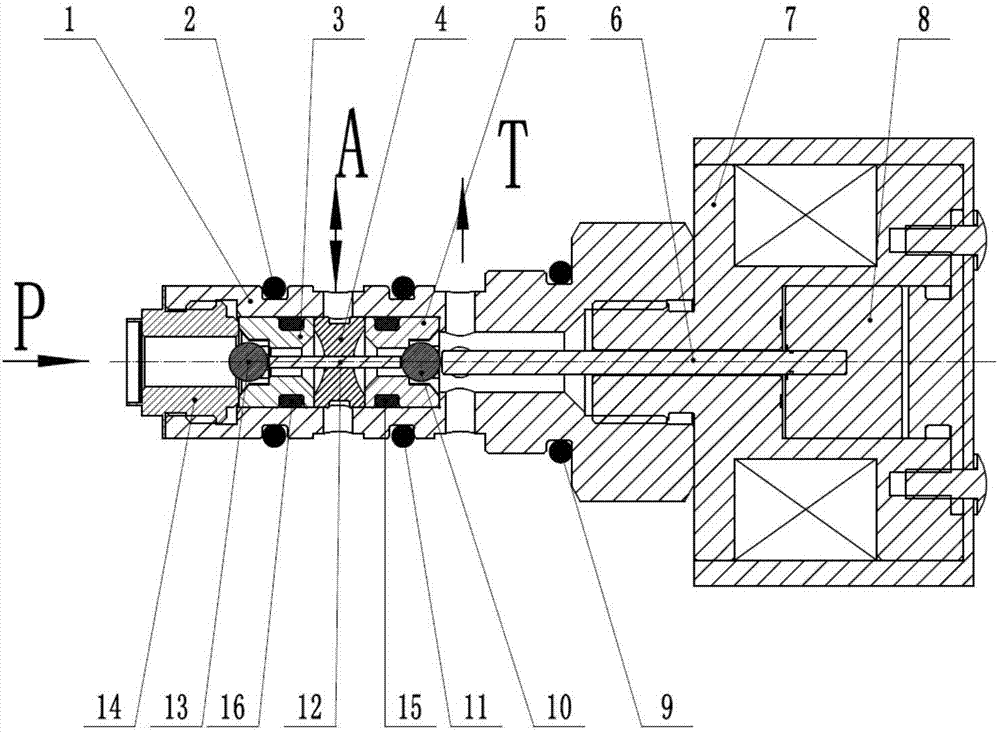
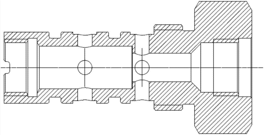
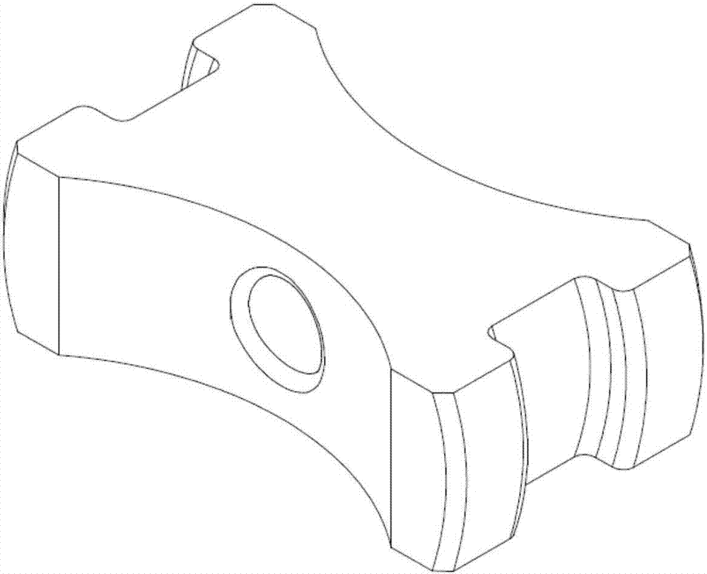
[0027] Such as figure 1 and figure 2 As shown, a detachable two-position three-way ball valve structure includes a valve sleeve, and a left steel ball 13, a left steel ball seat 3, a separation pin seat 4, a separation pin 12, and a right steel ball seat 5 are arranged in the valve sleeve. , right steel ball 10, armature 8, push rod 6 and screen bolt 14, the outer side of described armature 8 is arranged to be used to control the electromagnet assembly of armature 8 action, and described armature 8 is connected with push rod 6, and described push rod The end of 6 is connected with the right end of right steel ball 10, and described right steel ball 10 is positioned at the through hole of right steel ball seat 5, and the left end of described right steel ball 10 is connected with the right end of separating pin 12, and described separating pin 12 is installed on the separation pin seat 4, the left end of the separation pin 12 is connected with the left steel ball 13, and the ...


PUM


Abstract

The invention discloses a detachable type two-position three-way ball valve structure. The structure comprises a valve sleeve, a left steel ball, a left steel ball base, a separation pin base, a separation pin, a right steel ball base, a right steel ball, an armature, a push rod and a filter net bolt are arranged in the valve sleeve, a boss structure is arranged in the valve sleeve, an outer thread structure is arranged on the filter net bolt, and is in tight fit with an inner thread structure in the valve sleeve, and through the thread screwing manner, the filter net bolt is inwards extruded until the filter net bolt, the left steel ball base, the separation pin base, the right steel ball base and the valve sleeve boss surface are in tight fit. The steel ball bases and the separation pin base are in small-gap fit with the valve sleeve, subsequent detaching is facilitated, the boss is moved to the right end from the middle, finishing can be achieved only through one-time machining, no breaking opening exists in the middle of the boss, an annular groove is formed in the periphery of the separation pin base, oil in an opening A can conveniently directly enter the valve sleeve from the groove, and the liquid resistance is reduced.

Description

technical field [0001] The invention relates to a detachable ball valve structure. Background technique [0002] High-speed on-off valve is a typical digital valve in the hydraulic field at present. Due to its strong anti-pollution ability, fast opening and closing characteristics and strong anti-interference ability, it is currently widely used in various hydraulic systems, such as vehicle Advanced ABS anti-lock braking system, fuel injection system, etc. Most of the high-speed on-off valves with two-way three-way function on the market are spring-returning slide valve structures. As we all know, slide valves will inevitably cause leakage, especially in high-pressure situations. Moreover, the cooperation relationship between the slide valve and the valve sleeve will directly affect the leakage and working frequency response. If the fit is too loose, the leakage problem will not be controlled, and if the fit is too tight, the resistance of the valve core will increase, whi...

Claims


Application Information

Patent Timeline
Patent Type & Authority Applications(China)
IPC IPC(8): F16K11/056F16K31/06
CPCF16K11/056F16K31/0631
Inventor 张斌蔚晓英钟麒吕梅明江君杨华勇马吉恩
Owner ZHEJIANG UNIV
Why Eureka
Try Eureka