Driving method and driving device of display panel

A display panel and driving method technology, applied to static indicators, instruments, etc., can solve problems such as inconsistencies in effective charging time, achieve the same process requirements, improve the color shift problem, and keep the product cost unchanged

Active Publication Date: 2017-12-19
HKC CORP LTD +1
View PDF10 Cites 23 Cited by
  • Summary
  • Abstract
  • Description
  • Claims
  • Application Information

AI Technical Summary

Problems solved by technology

[0004] Based on this, it is necessary to provide a driving method and a driving device for a display panel for the problem

Method used


Image

  • Driving method and driving device of display panel
  • Driving method and driving device of display panel
  • Driving method and driving device of display panel

Examples


Embodiment Construction

[0063] In order to facilitate the understanding of the present invention, the present invention will be described more fully below with reference to the associated drawings. Preferred embodiments of the invention are shown in the accompanying drawings. However, the present invention can be embodied in many different forms and is not limited to the embodiments described herein. On the contrary, these embodiments are provided to make the understanding of the disclosure of the present invention more thorough and comprehensive.

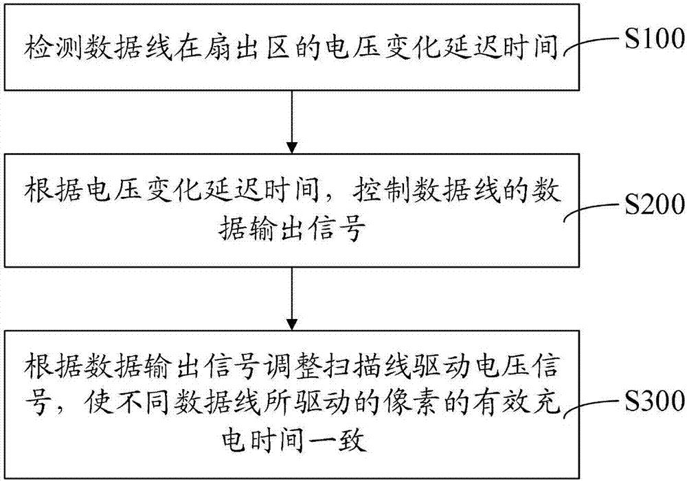
[0064] figure 1 It is a flowchart of a method for driving a display panel according to an embodiment, and the method includes:

[0065] Step S100: Detect the voltage change delay time of the data line in the fan-out area. When TFT-LCD is designing the pixel matrix, the output wiring of the driver IC needs to be centrally laid out in the press-fit area, and the handling method is fan-out layout. Therefore, the distances from the output of the driver IC...


PUM


Abstract

The invention relates to a driving method and driving device of a display panel. The driving method comprises a step of detecting a voltage change delay time of a data line at a fan out area, a step of controlling the data output signal of the data line according to the voltage change delay time, and a step of adjusting a scanning line to drive a voltage signal according to the data output signal such that the effective charging times of pixels driven by different data lines in a same scanning line are consistent. According to the above driving method and driving device of a display panel, through changing falling edge times of data output signals on different data lines, a color cast problem brought by different voltage change time delays is improved, and the optical grade of a product is improved. Moreover, process demands and the cost of the product are not changed according to the method.

Description

technical field [0001] The present invention relates to the field of display technology, in particular to a driving method and a driving device of a display panel. Background technique [0002] Thin-film-transistor liquid crystal display (TFT-LCD) technology needs to carry out centralized layout processing of the output wiring of the driver IC in the bonding area when performing display panel matrix design, and the processing method is fan Out (fan-out) layout. Therefore, the distance from the output of the driver IC to the data lines in the display area is not equal, so that the impedance of the data lines in the fan-out area cannot be consistent, resulting in a different degree of voltage change delay (RC delay) for each data line. On the same scanning line, the inconsistency of the effective charging time of the pixels driven by each data line causes color shift (colorshift). [0003] The traditional solution for improving color shift includes making the traces of the d...

Claims


Application Information

Patent Timeline
IPC IPC(8): G09G3/36
CPCG09G3/36G09G3/3611G09G2320/0242G09G3/3266G09G3/3275G09G3/3685G09G2300/0426G09G2310/08G09G2320/0223G09G3/3258G09G3/3688
Inventor 胡水秀
Owner HKC CORP LTD
Why Eureka
Try Eureka