Antenna rotation base and antenna thereof

A technology of rotating base and antenna, applied in the direction of antenna, antenna parts, antenna support/installation device, etc., can solve the problem of inconvenient adjustment, inability to adjust the height of the antenna, etc., to achieve rapid search or adjustment, convenient use, and structural design simple effect

Inactive Publication Date: 2017-12-19
海南同诺文化科技有限公司
View PDF7 Cites 5 Cited by
  • Summary
  • Abstract
  • Description
  • Claims
  • Application Information

AI Technical Summary

Problems solved by technology

[0003] After the antenna is installed, it needs to be adjusted to obtain the best receiving surface. The traditional antenna installation base is generally fixed, which is inconvenient to adjust. There are also some installation bases that can be rotated, but the height of the antenna cannot be adjusted.

Method used


Image

  • Antenna rotation base and antenna thereof
  • Antenna rotation base and antenna thereof
  • Antenna rotation base and antenna thereof

Examples


Embodiment Construction

[0017] The following will clearly and completely describe the technical solutions in the embodiments of the present invention with reference to the accompanying drawings in the embodiments of the present invention. Obviously, the described embodiments are only some, not all, embodiments of the present invention. Based on the embodiments of the present invention, all other embodiments obtained by persons of ordinary skill in the art without making creative efforts belong to the protection scope of the present invention.

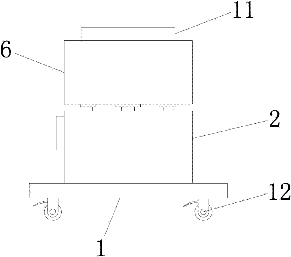
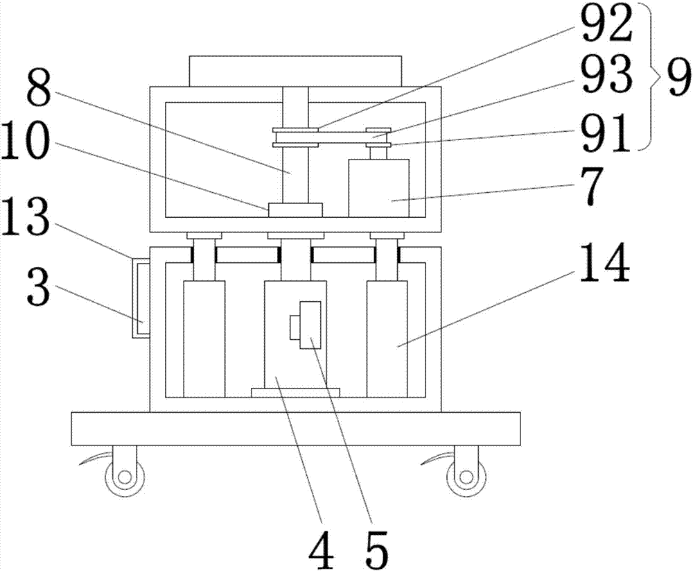
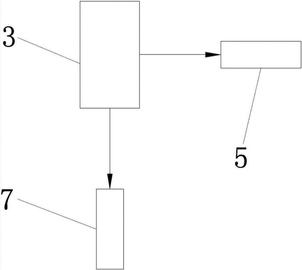
[0018] see Figure 1-3 , the present invention provides a technical solution: a rotating antenna base, including a bottom plate 1, a first box 2 is arranged on the upper surface of the bottom plate 1, and a PLC is fixedly installed on the outer wall of the first box 2 A controller 3, a hydraulic cylinder 4 is fixedly installed in the inner cavity of the first box body 2, and a solenoid valve 5 is fixedly installed on the hydraulic cylinder 4, and the solenoid ...


PUM


Abstract

The invention discloses an antenna rotation base. The antenna rotation base comprises a bottom plate, wherein a first box body is arranged on an upper surface of the bottom plate, a programmable logic controller (PLC) is fixedly arranged on an outer side wall of the first box body, a solenoid valve is fixedly arranged on a hydraulic cylinder and is electrically connected with the PLC via a wire, a servo motor and a rotation shaft are arranged in an inner cavity of a second box body, the servo motor is electrically connected with the PLC via a wire and is in transfer connection with the rotation shaft via a transmission device, and a top end of the rotation shaft penetrates through a top plate of the second box body and is fixedly connected with a center of an installation rotary disc. The invention also discloses an antenna, and the antenna comprises the antenna rotation base. The antenna rotation base and the antenna thereof are simple in structural design and are convenient to use, the antenna can be driven to rotate by the antenna rotation base, the height of the antenna can be adjusted, and the optimal receiving surface of the antenna can be rapidly found out or the antenna can be rapidly adjusted to the optimal receiving surface by combination of the antenna and the antenna rotation base.

Description

technical field [0001] The invention relates to the technical field of antenna equipment, in particular to an antenna rotating base and an antenna thereof. Background technique [0002] An antenna is a transformer that transforms a guided wave propagating on a transmission line into an electromagnetic wave propagating in an unbounded medium, or vice versa. A component used in radio equipment to transmit or receive electromagnetic waves. Engineering systems such as radio communication, broadcasting, television, radar, navigation, electronic countermeasures, remote sensing, and radio astronomy, which use electromagnetic waves to transmit information, rely on antennas to work. In addition, in terms of transmitting energy with electromagnetic waves, non-signal energy radiation also requires antennas. Generally, antennas are reversible, that is, the same antenna can be used as both a transmitting antenna and a receiving antenna. The basic characteristic parameters of the same ...

Claims


Application Information

Patent Timeline
Patent Type & Authority Applications(China)
IPC IPC(8): H01Q1/12H01Q3/04
CPCH01Q1/12H01Q1/125H01Q3/04
Inventor 李响
Owner 海南同诺文化科技有限公司
Why Eureka
Try Eureka