Laser for improving asymmetric light spot output

An asymmetric laser technology, applied in the field of lasers, can solve problems such as output spot asymmetry, achieve the effect of improving spot asymmetry, wide application range, and low negative effects

Active Publication Date: 2017-12-19
CHANGCHUN UNIV OF SCI & TECH
View PDF4 Cites 1 Cited by
  • Summary
  • Abstract
  • Description
  • Claims
  • Application Information

AI Technical Summary

Problems solved by technology

[0004] In order to solve the problems existing in the prior art, the present invention provides a laser that improves the output of the asymmetric spot. The

Method used


Image

  • Laser for improving asymmetric light spot output
  • Laser for improving asymmetric light spot output
  • Laser for improving asymmetric light spot output

Examples


Example Embodiment

[0019] The present invention will be further described in detail below with reference to the drawings and embodiments.

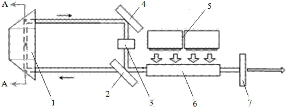
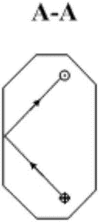
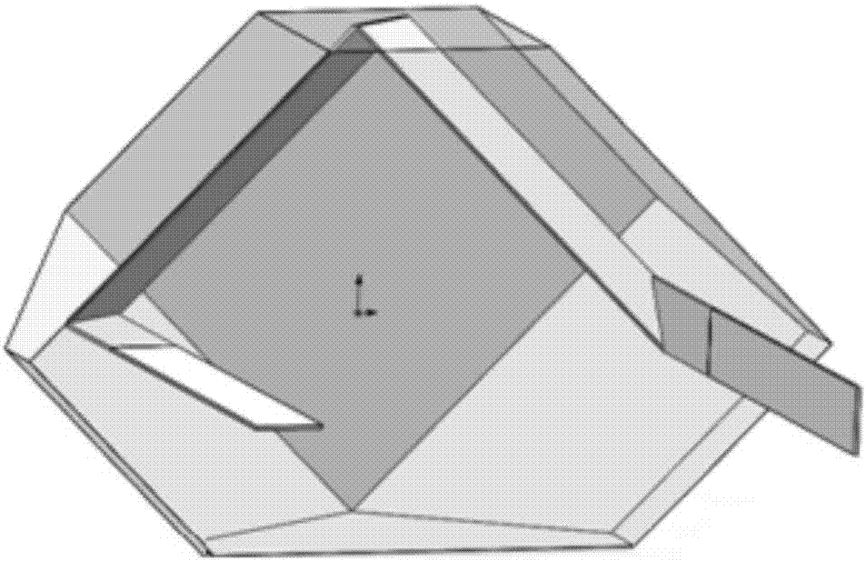
[0020] Such as figure 1 As shown, the laser device diagram for improving the asymmetric light spot output of the present invention includes a polygonal prism 1, a polarizer 2, a 90-degree linear polarization rotator 3, a total reflection mirror 4, a pump module 5, a gain medium 6 and an output mirror 7. Among them, the polarizer 2, the polygonal prism 1, the total reflection mirror 4, the 90-degree linear polarization rotator 3 and the output mirror 7 together constitute an optical resonant cavity. Generally, the optical resonant cavity includes a mirror module A and a reflection mirror module A and a reflection mirror respectively provided at both ends of the cavity. Mirror module B, that is, the output mirror 7 constitutes the mirror module A on the side of the optical resonant cavity. The polarizer 2, the polygonal prism 1, the total reflection mirror 4 and t...


PUM


Abstract

A laser for improving asymmetric light spot output relates to the technical field of lasers, and the problem of asymmetric laser output light spot of the laser is solved. The laser comprises a pumping module, a grain medium and an optical resonant cavity, wherein the optical resonant cavity comprise an output mirror, a polarization film, a multi-surface prism, a total-reflection mirror and a 90-degree linear polarization rotator, wherein a light beam is totally reflected for three times by the multi-surface prism to achieve 90-degree image rotating of the light beam, the light bream oscillates for many times in the optical resonant cavity and is subjected to 90-degree image rotating by the multi-surface mirror, the problem of non-uniform energy distribution of an original light beam is changed, and symmetric light spot output is obtained; and meanwhile, residual pumping loss is not generated, the negative effect is low, and the laser is wide in application range.

Description

technical field [0001] The invention relates to the technical field of lasers, in particular to a laser for improving asymmetric light spot output. Background technique [0002] The symmetry of laser output has been an important assessment index for laser applications since the invention of lasers. The inhomogeneity of the pump light generated by the pump module or the pump source has a great influence on the symmetry of the laser output. At present, the main ways to improve the symmetry of the laser output spot are to limit the laser mode and improve the symmetry of the pump light field. [0003] The method of limiting the laser mode has low pump light utilization rate and low conversion efficiency, which will waste most of the pump light energy. In order to obtain higher energy output, it is necessary to use stronger pump light for pumping, which leads to the laser A series of problems such as heat dissipation and birefringence. Improving the symmetry of the pump light ...

Claims


Application Information

Patent Timeline
IPC IPC(8): H01S3/136H01S3/13
CPCH01S3/13H01S3/136
Inventor 王超李述涛陈薪羽于永吉董渊吴春婷王子健金光勇
Owner CHANGCHUN UNIV OF SCI & TECH
Why Eureka
Try Eureka