Detuning magnetic resonance radio frequency coil without external direct current circuit

A technology of radio frequency coils and DC lines, applied in magnetic resonance measurement, medical science, sensors, etc., can solve problems affecting coil debugging and imaging performance, reducing coil imaging performance, coil heating, etc., and achieves a small impact on the uniformity of the main magnetic field, The effect of taking up less space and reducing negative effects

Active Publication Date: 2013-07-03
SHANGHAI CHENGUANG MEDICAL TECH
6 Cites 2 Cited by

AI-Extracted Technical Summary

Problems solved by technology

[0009] 1. In terms of space, it is necessary to reserve a place for the DC line; especially now that the number of coil channels is increasing (there are more and more coils with dozens of units), this problem is becoming more and more prominent
[0010] 2. In order to reduce the length of the DC line, many chokes need to be added. As shown in item 1, more and more chokes require more and more space;
[0011] 3. Coupling of DC line, ...

Method used

As shown in Figure 3, the present embodiment does not have the detuning magnetic resonance radio frequency coil of external direct current line and comprises the active detuning circuit and resonant capacitor of series connection, is provided with by printed circuit board between active detuning circuit and resonant capacitor Two parallel resonant inductors formed by the copper-clad copper, and the two parallel resonant inductors form a loop and are connected to the DC power supply driving the active detuning circuit. In most ...

Abstract

The invention discloses a detuning magnetic resonance radio frequency coil without an external direct current circuit. The detuning magnetic resonance radio frequency coil comprises a driving detuning circuit and a resonance capacitor, wherein the driving detuning circuit and the resonance capacitor are in serial connection, two parallel resonance inductors formed by coated copper of a printed circuit board are arranged between the driving detuning circuit and the resonance capacitor, and the two parallel resonance inductor form a loop and are connected with a direct-current power supply used for driving the driving detuning circuit. The detuning magnetic resonance radio frequency coil has the advantages of mutually offsetting magnetic fields generated by direct current to the maximum degree and being small in effect on evenness of a main field, small in cross interference, good in radio frequency characteristic, small in occupancy and simple in circuit structure.

Application Domain

Diagnostic recording/measuringSensors +1

Technology Topic

PhysicsInductor +10

Image

  • Detuning magnetic resonance radio frequency coil without external direct current circuit
  • Detuning magnetic resonance radio frequency coil without external direct current circuit
  • Detuning magnetic resonance radio frequency coil without external direct current circuit

Examples

  • Experimental program(2)

Example Embodiment

[0028] Embodiment one:
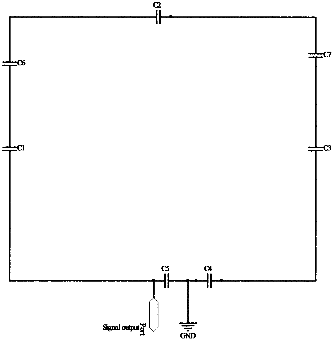
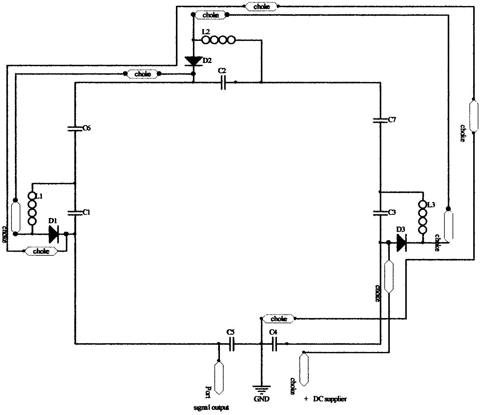
[0029] like image 3 As shown, in this embodiment, the detunable magnetic resonance radio frequency coil without an external DC circuit includes an active detuning circuit and a resonant capacitor connected in series, and there are two copper-coated printed circuit boards between the active detuning circuit and the resonant capacitor. There are parallel resonant inductors, and the two parallel resonant inductors form a loop and are connected to the DC power supply driving the active detuning circuit. In most radio frequency coils, the inductance of the coil unit is one or two layers of copper in the double-layer PCB, that is, one or two layers of the top layer and the bottom layer of the double-sided PCB together form the inductance of the coil unit. The present invention uses such double-layer copper cladding, and through appropriate design changes, direct current can flow through the original radio frequency signal lines, thereby eliminating additional direct current lines and reducing the above-mentioned various negative effects.
[0030]In this embodiment, one end of the two parallel resonant inductors is connected together through an active detuning circuit located at the output end of the magnetic resonance radio frequency coil, and the other ends of the two parallel resonant inductors are respectively grounded through a grounding capacitor, and one grounding capacitor is connected to a choke The coils are connected in parallel, and the non-ground terminal of the other grounded capacitor is connected to the DC power supply driving the active detuning circuit. In this embodiment, one resonant inductance is 1, 2, 3, 4, 5, and the other resonant inductance is 11, 21, 31, 41, 51, and the resonant inductances 5 and 51 pass through the active detuning at the output end of the magnetic resonance radio frequency coil The circuit is connected, the resonant inductor 1 is grounded through the grounding capacitor C41, the resonant inductor 11 is grounded through the grounding capacitor C4, the grounding capacitor C4 is connected in parallel with a choke coil choke10, and the non-grounded end of the grounding capacitor C41 is connected to the DC power supply ( DC supplier) connected. The DC circuit where the DC current completely passes through the RF circuit is: +DC supplier (DC power supply) → choke1 → resonant inductor 1 → diode D3 → inductor L3 → resonant inductor 2 → choke2 → resonant inductor 3 → inductor L2 → diode D2 → resonance Inductor 4→choke4→resonant inductor 5→inductor L1→diode D1→choke5→resonant inductor 51→choke6→resonant inductor 41→choke7→resonant inductor 31→choke8→resonant inductor 21→choke9→resonant inductor 11→choke10→GND.
[0031] This embodiment not only does not introduce additional DC wires, but also the distance between the two wires of the DC wires is very small (the bottom layer and the top layer of the flexible double-layer PCB are used as inductance 1, 2, 3, 4, 5 and inductance 11 respectively. , 21, 31, 41, 51, the distance between them is <1mm), almost no additional magnetic field will be generated to affect the uniformity of the magnetic resonance magnetic field.
[0032] In this embodiment, the resonant capacitors are respectively connected in parallel with one choke coil. For example, the resonant capacitor C7 is connected in parallel with a choke coil choke7, the resonant capacitor C71 is connected in parallel with a choke coil choke2, the resonant capacitor C6 is connected in parallel with a choke coil choke6, and the resonant capacitor C61 is connected in parallel with a choke coil choke4. In addition, a series choke coil choke1 is provided at the input end of a DC power supply (DC supplier).
[0033] In this embodiment, among the two parallel resonant inductors, one resonant inductor is arranged on the top layer of the printed circuit board, and the other resonant inductor is arranged on the bottom layer of the printed circuit board. Additionally, the present embodiments are not entirely limited to a detunable magnetic resonance RF coil. A direct current circuit can also be formed between a plurality of detunable magnetic resonance radio frequency coils adjacent to each other without introducing any additional direct current lines by adopting this embodiment, and the uniformity of the main magnetic field will not be affected by the existence of direct current. advantage.
[0034] In this embodiment, the active detuning circuit includes two first capacitors respectively used to connect to one of the two resonant inductors, the two ends of the two first capacitors are respectively connected in parallel through the second capacitor, and one first A capacitor is connected in parallel with a choke coil, and another first capacitor, an inductor and a diode are sequentially connected in series to form a basic detuning circuit. Taking the first active detuning circuit on the input side of the DC power supply (DC supplier) driving the active detuning circuit as an example, the active detuning circuit includes two first capacitors C3 and C31, the input terminal of the first capacitor C3 and the resonant inductor 11 , the output end is connected to the resonant inductor 21 , the input end of the first capacitor C31 is connected to the resonant inductor 1 , and the output end is connected to the resonant inductor 2 . One ends of the first capacitors C3 and C31 are connected in parallel through the second capacitor C32, and the other ends of the first capacitors C3 and C31 are connected in parallel through the second capacitor C33. The first capacitor C3 is connected in parallel with a choke coil choke9; the first capacitor C31 is sequentially connected in series with the inductor L3 and the diode D3 to form a basic detuning loop. The structures of other active detuning circuits are the same and will not be repeated here.

Example Embodiment

[0035] Embodiment two:
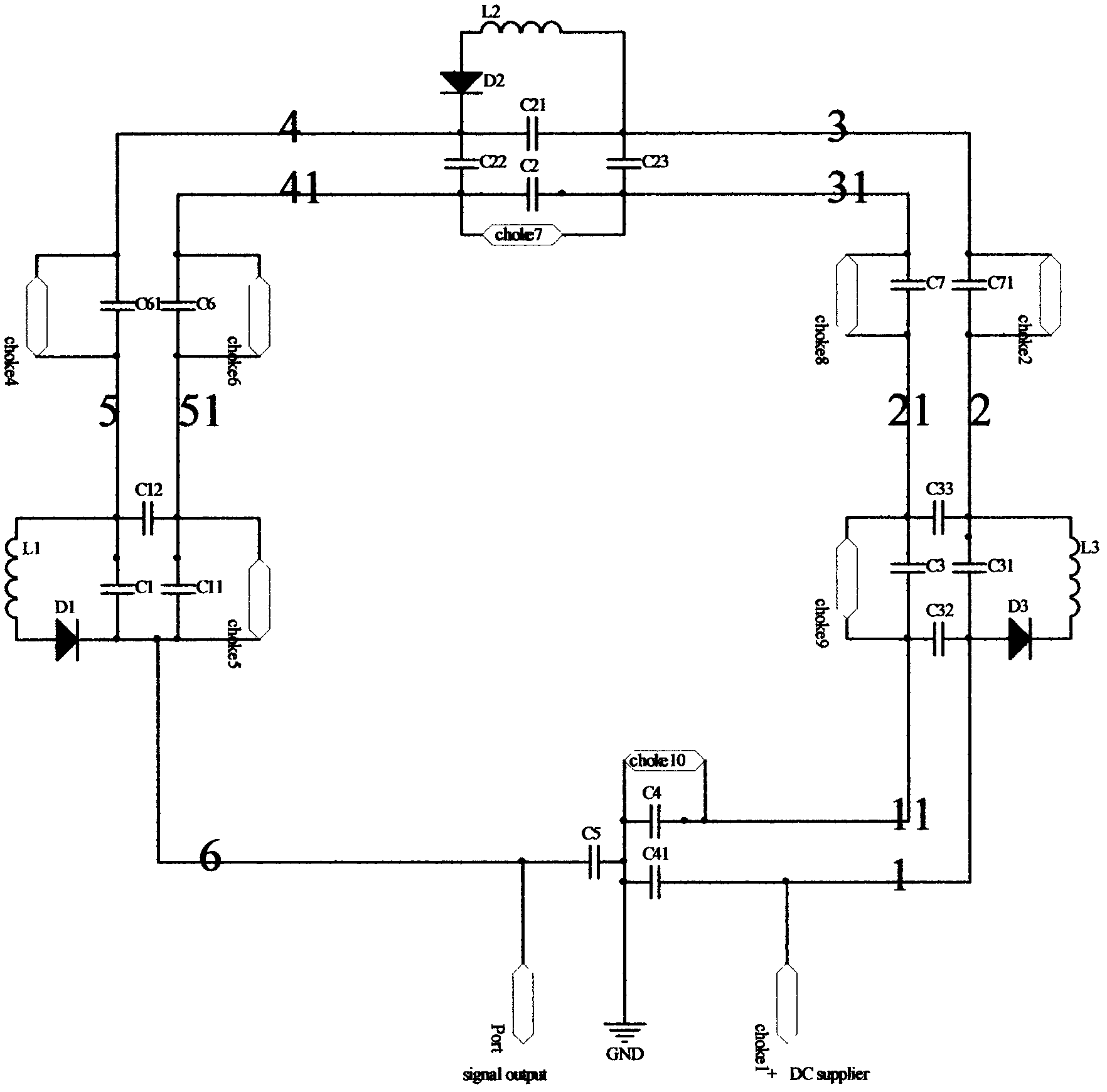
[0036] like Figure 4 As shown, this embodiment is basically the same as Embodiment 1, the difference is that the active detuning circuit adopts two parallel basic detuning circuits: the active detuning circuit includes two resonant inductances used to connect with one of the two resonant inductances The connected first capacitors, the two first capacitors are respectively connected in series with the inductor and the diode in sequence to form two parallel basic detuning circuits. Taking the first active detuning circuit on the input side of the DC power supply (DC supplier) driving the active detuning circuit as an example, the active detuning circuit includes two first capacitors C3 and C31, the input terminal of the first capacitor C3 and the resonant inductor 11 , the output end is connected to the resonant inductor 21 , the input end of the first capacitor C31 is connected to the resonant inductor 1 , and the output end is connected to the resonant inductor 2 . The first capacitor C3, the inductor L33, and the diode D33 are sequentially connected in series to form the first basic detuning circuit; the first capacitor C31, the inductor L3, and the diode D3 are connected in series to form the first basic detuning circuit. A second basic detuned circuit parallel to the basic detuned circuit.

PUM

no PUM

Description & Claims & Application Information

We can also present the details of the Description, Claims and Application information to help users get a comprehensive understanding of the technical details of the patent, such as background art, summary of invention, brief description of drawings, description of embodiments, and other original content. On the other hand, users can also determine the specific scope of protection of the technology through the list of claims; as well as understand the changes in the life cycle of the technology with the presentation of the patent timeline. Login to view more.

Similar technology patents

Method and device for decoding data streams

InactiveCN105828083ASimple circuit structureSave FPGA resources
Owner:ZTE CORP

Classification and recommendation of technical efficacy words

  • Simple circuit structure
  • reduce negative effects

Abnormal event monitoring method and system based on radio frequency identification positioning

InactiveCN103914716Asave time and resourcesreduce negative effects
Owner:BEIJING INST OF COMP TECH & APPL

Device for preparing bio-oil from waste manmade boards by thermochemical clean conversion

InactiveCN101955786Areduce negative effectsSimple structure
Owner:BEIJING FORESTRY UNIVERSITY

Plant functional combination for planting in arenaceous fluctuating zone of reservoir area

InactiveCN102177781AImproves cohesion and soil organic matter contentreduce negative effects
Owner:NINGBO INST OF TECH ZHEJIANG UNIV ZHEJIANG

System score coverage adjusting and optimizing method

PendingCN113836381Acomprehensive coveragereduce negative effects
Owner:广东南方信息安全研究院

Laser for improving asymmetric light spot output

ActiveCN107492784AImprove spot asymmetryreduce negative effects
Owner:CHANGCHUN UNIV OF SCI & TECH
Why Eureka
Try Eureka