
High-efficiency liquid filling machine

A filling machine and liquid technology, used in liquid bottling, liquid processing, cleaning of filling devices, etc., can solve the problems of filling liquid precipitation, dust falling, uneven filling liquid, etc., to reduce vibration and ensure mixing , the effect of protecting the service life

Inactive Publication Date: 2017-12-22
朱淑君
View PDF0 Cites 11 Cited by
  • Summary
  • Abstract
  • Description
  • Claims
  • Application Information

AI Technical Summary

Problems solved by technology

[0003] When the current filling machine is filling liquid, because it does not stir the filling liquid, it will cause precipitation inside the filling liquid, or the filling liquid will be uneven, which will seriously affect the quality of the product, and During the filling process, the nozzles are generally exposed, so that dust will fall on the surface of the nozzles, and filling in this way cannot protect the dust from falling in.

Method used


Image

  • High-efficiency liquid filling machine
  • High-efficiency liquid filling machine
  • High-efficiency liquid filling machine

Examples


Embodiment Construction

[0017] It should be noted that, in the case of no conflict, the embodiments of the present invention and the features in the embodiments can be combined with each other.

[0018] In describing the present invention, it should be understood that the terms "center", "longitudinal", "transverse", "upper", "lower", "front", "rear", "left", "right", " The orientations or positional relationships indicated by "vertical", "horizontal", "top", "bottom", "inner" and "outer" are based on the orientations or positional relationships shown in the drawings, and are only for the convenience of describing the present invention and Simplified descriptions, rather than indicating or implying that the device or element referred to must have a particular orientation, be constructed and operate in a particular orientation, and thus should not be construed as limiting the invention. In addition, the terms "first", "second", etc. are used for descriptive purposes only, and should not be understood ...


PUM


Abstract

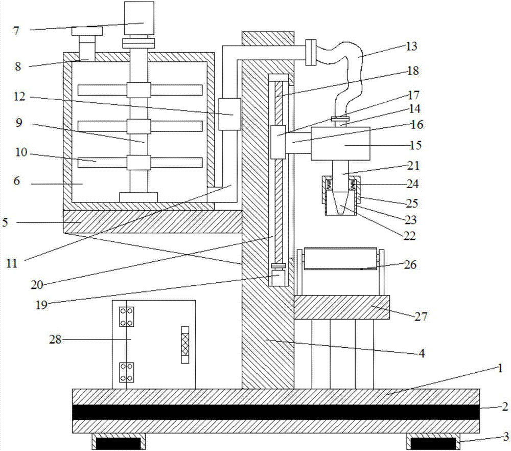
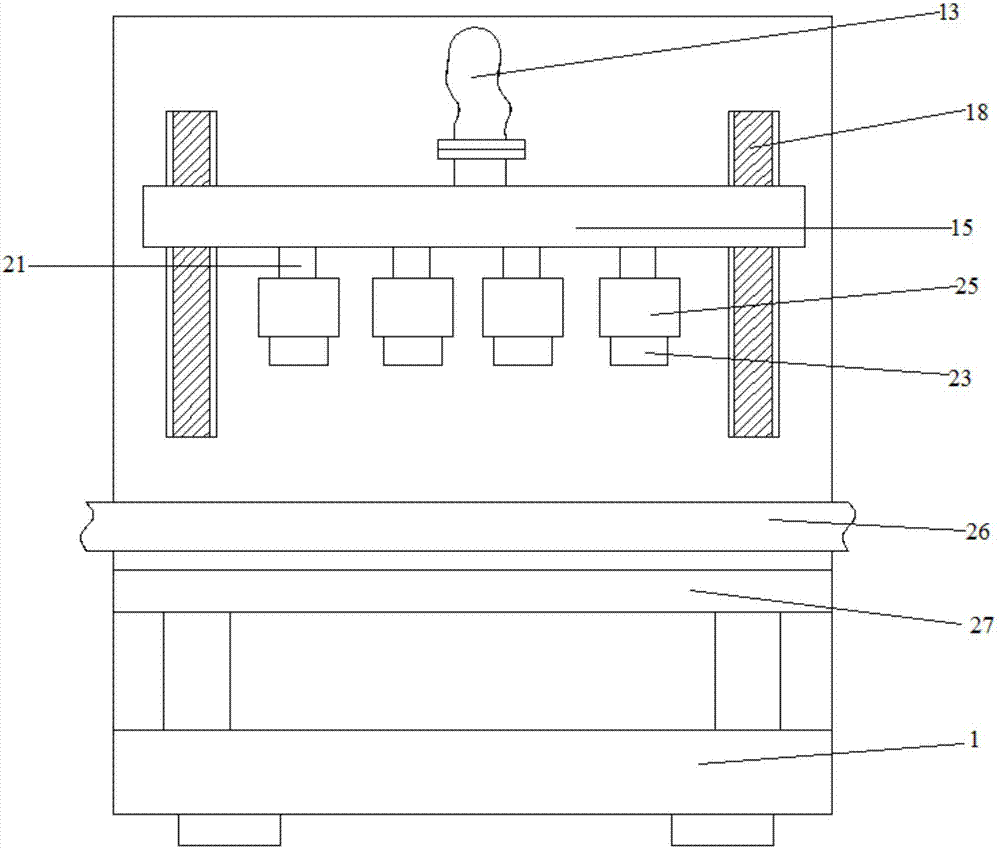
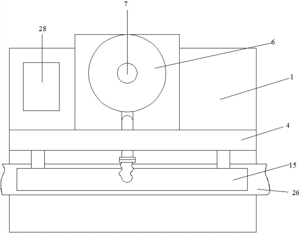
The invention discloses a high-efficiency liquid filling machine. The high-efficiency liquid filling machine comprises a base. A supporting plate is arranged in the middle of the upper side of the base. The lower end of the left side of the supporting plate is provided with a fixed plate. The front end of the lower side of the fixed plate is provided with an electric control cabinet. A liquid storage cavity is arranged on the upper side of the fixed plate. The right side of the liquid storage cavity is provided with a first connecting pipe. The lower end of the right side of the first connecting pipe is provided with a connecting hose. The lower side of the connecting hose is provided with a second connecting pipe. The lower side of the second connecting pipe is provided with a connecting cavity. The front and rear sides of the left side of the connecting cavity are provided with connecting rods. The left sides of the connecting rods are provided with a sliding block. The sliding block is internally provided with a lead screw. The lower side of the lead screw is provided with a second motor. The lower side of the connecting cavity is provided with a liquid adding pipe. The lower side of the liquid adding pipe is provided with a nozzle. The outer side of the nozzle is provided with a connecting cover. The four corners of the rear side of the connecting cover are provided with springs. The outer sides of the springs are provided with a fixing cover. A conveyor belt is arranged under the nozzle. A connecting plate is arranged under the conveyor belt. The high-efficiency liquid filling machine can effectively and conveniently conduct liquid filling and can effectively prevent the nozzle from being damaged during liquid filling.

Description

technical field [0001] The invention relates to a processing equipment, in particular to a high-efficiency liquid filling machine. Background technique [0002] Filling machines are mainly a small category of products in packaging machines. From the perspective of packaging materials, they can be divided into liquid filling machines, paste filling machines, powder filling machines, and particle filling machines; from the degree of automation of production It is divided into semi-automatic filling machine and fully automatic filling production line. Recently, with the QS certification of food, edible oil manufacturers have begun to pay attention to product quality and packaging, so the oil filling machine has a prominent position in the filling machine. [0003] When the current filling machine is filling liquid, because it does not stir the filling liquid, it will cause precipitation inside the filling liquid, or the filling liquid will be uneven, which will seriously affec...

Claims


Application Information

Patent Timeline
IPC IPC(8): B67C3/00B67C3/26B67C3/24B67C3/22B65G43/00B01F7/18
CPCB65G43/00B67C3/001B67C3/22B67C3/24B67C3/26B01F27/90
Inventor 朱淑君
Owner 朱淑君
Learn More