Spray and aspirating device for construction in construction site
A spray dust reduction and construction site technology, applied in construction, use of liquid separating agent, road cleaning, etc., can solve the problems of large stress on the rotating part, damage to the rotating shaft bearing, and changes in the coaxiality of the rotating shaft and the matching hole, etc., to improve the coaxial , the effect of protecting the quality
- Summary
- Abstract
- Description
- Claims
- Application Information
AI Technical Summary
Problems solved by technology
Method used
Image
Examples
Embodiment 1
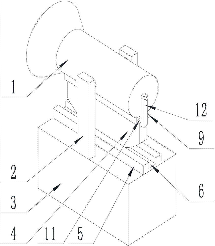
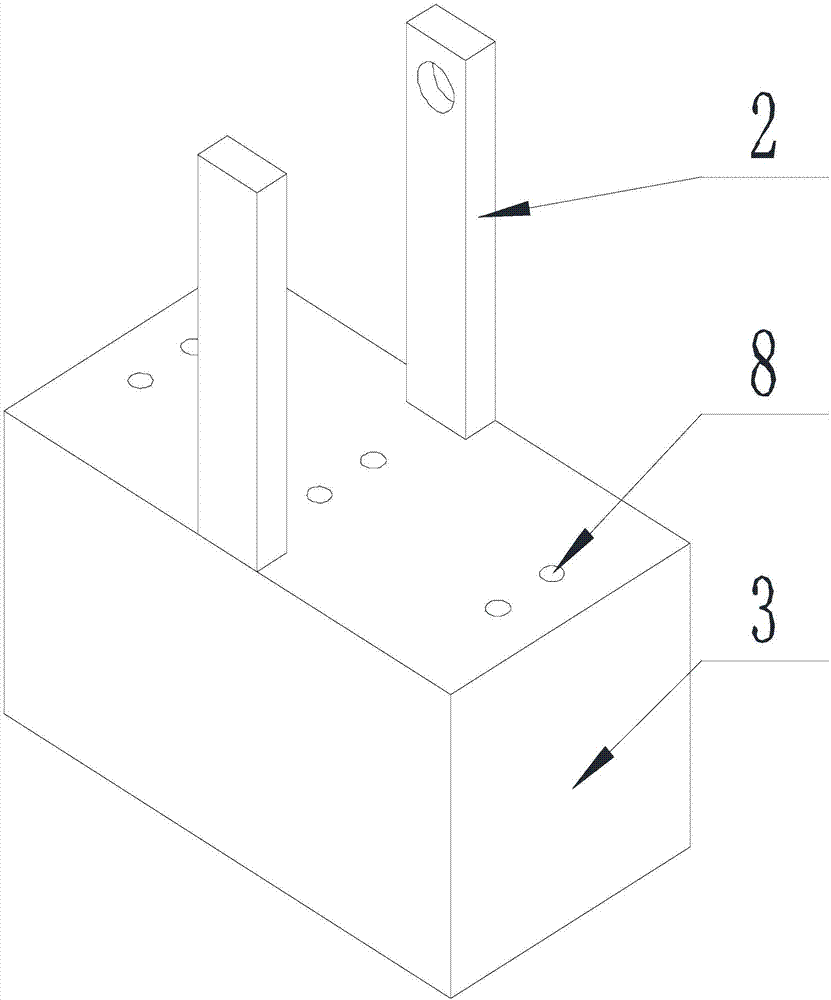
[0036] Such as Figure 1-Figure 7 As shown, the spray dust reduction device for construction site construction of the present invention includes a spray dust reduction machine. The spray dust reduction machine includes a spray tube 1, a bracket 2 and a mounting box 3 connected in sequence. The side wall of the spray tube 1 and the bracket 2 rotate Connected, the bracket 2 supports the spray cylinder 1 above the installation box 3, and a support plate 4 is provided on the side wall of the spray cylinder 1 near the end of the installation box 3, and the support plate 4 is parallel to the axis of the spray cylinder 1. And the end of the support plate 4 away from the spray canister 1 is an arc-shaped surface, the axis of the arc-shaped surface coincides with the rotation axis of the spray canister 1, and the arc-shaped surface is in contact with the end surface of the installation box 3 close to the spray canister 1.
[0037] Since the end of the support plate 4 far from the spray ca...
Embodiment 2
[0039] This embodiment is on the basis of Embodiment 1 to further illustrate the present invention.
[0040] Such as Figure 1-Figure 7 As shown, the spray dust suppression device for construction site construction of the present invention is provided with a limit block 5 on the end surface of the installation box 3 close to the spray cylinder 1, and a limit block 5 is provided on the end of the limit block 5 far away from the installation box 3 Slot 6, the axis of the limiting slot 6 is parallel to the axis of the spray canister 1, and in the orthographic projection of the upper surface of the installation box 3, the projection of the axis of the spray canister 1 coincides with the projection of the axis of the limiting slot 6, and the support plate 4 The upper end far away from the spray canister 1 is located in the limiting groove 6, and the arc surface is in contact with the bottom of the limiting groove 6, and the groove wall of the limiting groove 6 is in contact with the c...
Embodiment 3
[0047] This embodiment is on the basis of Embodiment 1 to further illustrate the present invention.
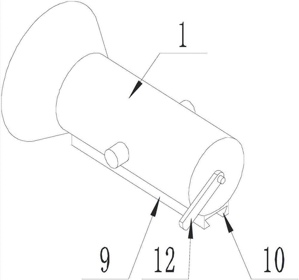
[0048] Such as Figure 1-Figure 7 As shown, the spray dust reduction device for construction site construction of the present invention is provided with a mounting block 9 on the side wall of the spray tube 1 near the end of the mounting box 3, and on the end of the mounting block 9 away from the spray tube 1 is provided Installation groove 10, the axis of the installation groove 10 is parallel to the axis of the spray cylinder 1, and the opening size of the installation groove 10 is smaller than the groove bottom size;
[0049] A connecting block 11 is provided on the support plate 4 at one end close to the spray barrel 1. The cross-sectional size of the connecting block 11 is consistent with the cross-sectional size of the mounting groove 10, and the connecting block 11 is matched with the mounting groove 10. Preferably, the installation groove 10 is a dovetail groove.
[0050] T...
PUM
 Abstract
Description
Claims
Application Information
 - R&D
- Intellectual Property
- Life Sciences
- Materials
- Tech Scout
- Unparalleled Data Quality
- Higher Quality Content
- 60% Fewer Hallucinations
Browse by: Latest US Patents, China's latest patents, Technical Efficacy Thesaurus, Application Domain, Technology Topic, Popular Technical Reports.
© 2025 PatSnap. All rights reserved.Legal|Privacy policy|Modern Slavery Act Transparency Statement|Sitemap|About US| Contact US: help@patsnap.com


