
Turbine

A technology of turbines and turbine rotors, applied in mechanical equipment, engine components, machines/engines, etc., can solve the problems of high power consumption, low efficiency and high price of low-grade waste heat recovery equipment, and achieve the effect of improving thermoelectric efficiency

Pending Publication Date: 2017-12-22
谢竞宁
View PDF0 Cites 6 Cited by
  • Summary
  • Abstract
  • Description
  • Claims
  • Application Information

AI Technical Summary

Problems solved by technology

[0002] In the field of low-grade waste heat recovery, the organic Rankine cycle technology is one of the main heat-power (electricity) technologies. Although compared with the traditional steam Rankine cycle power generation technology, the organic Rankine cycle technology has a simplified system and high efficiency, but The efficiency of low-grade waste heat recovery equipment is still low, and the investment payback period is long, which is one of the main factors restricting the development of low-grade waste heat recovery power generation industry
[0003] The existing organic Rankine cycle system that uses a magnetic levitation turbo expander to generate electricity, although the efficiency and life of the expander has been improved, the overall thermoelectric efficiency of the system is not high due to the low service life and efficiency of the auxiliary machine, especially for cycle workers. Mass pump, if the magnetic levitation centrifugal working medium pump is used, the power consumption is high and the price is high; if the ordinary working medium pump is used, the power consumption is high, the price is high, the service life is short, and the maintenance cost is high

Method used


Image

  • Turbine
  • Turbine
  • Turbine

Examples


Embodiment Construction

[0037] Embodiments of the invention are described in detail below, examples of which are illustrated in the accompanying drawings. The embodiments described below by referring to the figures are exemplary and are intended to explain the present invention and should not be construed as limiting the present invention.

[0038] In describing the present invention, it should be understood that the terms "center", "longitudinal", "transverse", "length", "width", "thickness", "upper", "lower", "front", " Back", "Left", "Right", "Vertical", "Horizontal", "Top", "Bottom", "Inner", "Outer", "Clockwise", "Counterclockwise", "Axial", The orientation or positional relationship indicated by "radial", "circumferential", etc. is based on the orientation or positional relationship shown in the drawings, and is only for the convenience of describing the present invention and simplifying the description, rather than indicating or implying the referred device or element Must be in a particular ...


PUM


Abstract

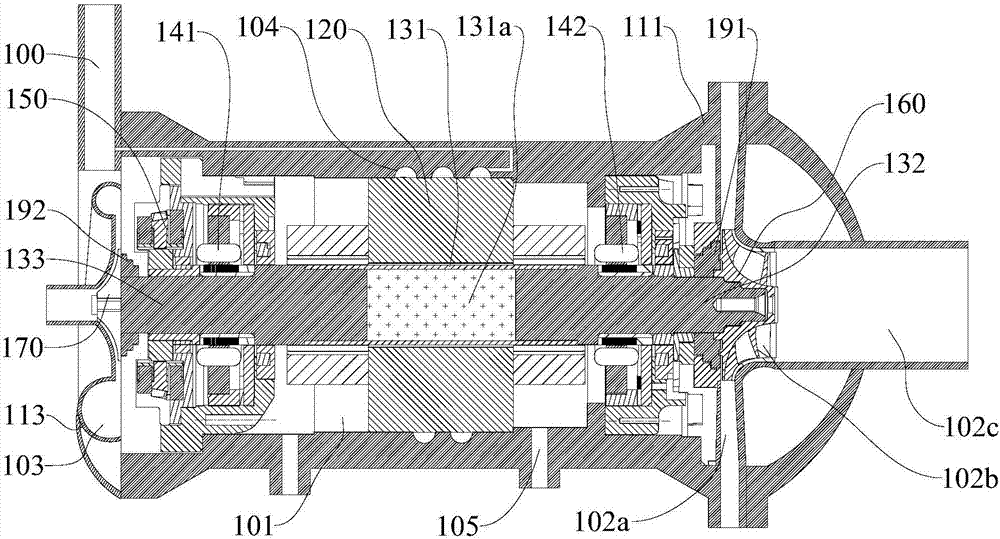
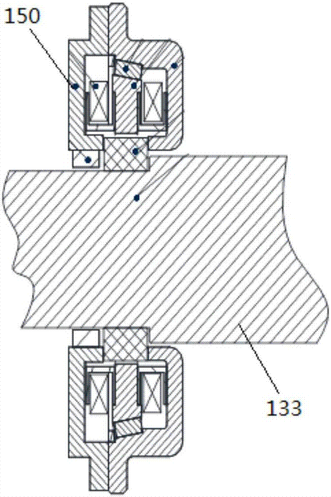
The invention discloses a turbine which comprises a motor shell, a volute, a working medium pump shell, a stator assembly, a rotor shaft, a front radial permanent magnet biased magnetic suspension bearing, a rear radial permanent magnet biased magnetic suspension bearing, an axial permanent magnet biased magnetic suspension bearing, an expansion turbine body, and a centrifugal impeller. The stator assembly is arranged on the inner wall of the motor shell. The front radial permanent magnet biased magnetic suspension bearing and the rear radial permanent magnet biased magnetic suspension bearing are arranged on the motor shell so as to support the rotor shaft. The axial permanent magnet biased magnetic suspension bearing is arranged on the motor shell so as to limit axial displacement of the rotor shaft. The expansion turbine body is located in a turbine work chamber, a gaseous working medium enters the turbine work chamber from an air inlet channel and is exhausted out of an exhaust channel after doing work on the expansion turbine body. The centrifugal impeller is arranged at the front end of the working medium pump rotor shaft and located in a third mounting space. The turbine provided by the invention is simple in structure, low in cost and high in thermoelectric efficiency.

Description

technical field [0001] The invention relates to the technical field of low-temperature waste heat recovery power generation, in particular to a turbine. Background technique [0002] In the field of low-grade waste heat recovery, the organic Rankine cycle technology is one of the main heat-power (electricity) technologies. Although compared with the traditional steam Rankine cycle power generation technology, the organic Rankine cycle technology has a simplified system and high efficiency, but The efficiency of low-grade waste heat recovery equipment is still low, and the investment payback period is long, which is one of the main factors restricting the development of low-grade waste heat recovery power generation industry. [0003] The existing organic Rankine cycle system that uses a magnetic levitation turbo expander to generate electricity, although the efficiency and life of the expander has been improved, the overall thermoelectric efficiency of the system is not high...

Claims


Application Information

Patent Timeline
IPC IPC(8): F01D15/10F01D25/12
CPCF01D15/10F01D25/12
Inventor 谢竞宁
Owner 谢竞宁
Learn More