
Worm gear reducer

A technology of worm reducer and worm gear, which is applied in the direction of gear transmission, belt/chain/gear, transmission parts, etc. It can solve the problems of vibration and noise, poor adjustment accuracy, and inconvenient operation, so as to achieve high adjustment accuracy and reduce wear Effect

Pending Publication Date: 2017-12-22
台州椒星传动设备有限公司
View PDF1 Cites 2 Cited by
  • Summary
  • Abstract
  • Description
  • Claims
  • Application Information

AI Technical Summary

Problems solved by technology

However, the above-mentioned worm gear reducer still has the following defects: Although the above-mentioned reducer is set to thicken the tooth thickness from the output end to the input end of the above-mentioned reducer, and is connected in the housing through the adjustment nut at the input end, by adjusting The nut cooperates with the thread of the casing to adjust the position of the adjusting nut in the casing, thereby driving the worm to move to eliminate the gap between the worm gear and worm, but since the adjusting nut is set at the input end, the input end also needs to be connected to the coupling and the motor , it is easy to interfere during adjustment, and the operation is more inconvenient
At the same time, because the thread of the adjusting nut is matched with the casing, that is to say, the adjustment can only be realized according to the pitch of the thread, the distance that the adjusting nut moves, that is, the adjusted pitch has a certain range, the adjustment accuracy is poor, and the adjusting nut There is a certain gap in the thread itself, and this gap cannot be eliminated by adjusting the rotation of the nut. Within the range of the gap, there will be a slight offset in both the radial direction and the axial direction, and the stability is poor. Therefore, there will still be a certain gap between the worm gear and worm, which will easily cause vibration and noise after running for a long time, and aggravate the wear of the worm gear.

Method used


Image

  • Worm gear reducer
  • Worm gear reducer
  • Worm gear reducer

Examples


Embodiment Construction

[0031] The following are specific embodiments of the present invention and in conjunction with the accompanying drawings, further describe the technical solution of the present invention, but the present invention is not limited to these embodiments.

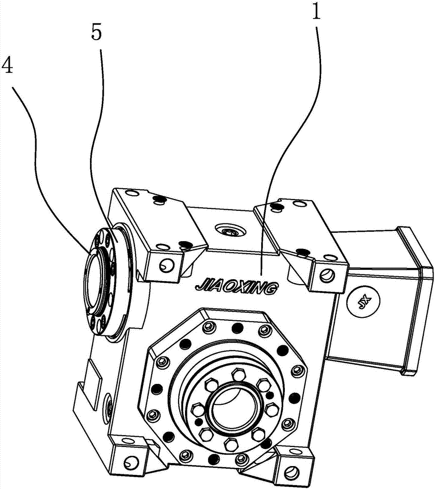
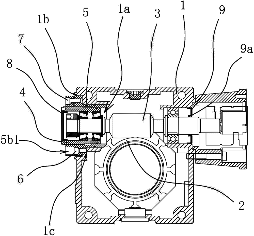
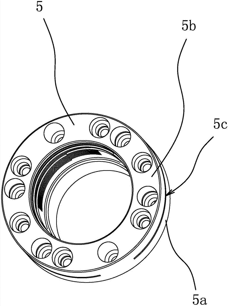
[0032] Such as figure 1 with 2 As shown, the worm gear reducer includes a housing 1, a worm gear 2, a worm 3, an adjusting sleeve 4, a locking sleeve 5, a locking bolt 1 6 and a locking bolt 2 7, and the worm gear 2 is arranged in the housing 1. The tooth thickness of the worm 3 gradually increases from the input end to the output end, and the worm 3 slides through the shaft hole 1a and meshes with the worm wheel 2 .

[0033] The housing 1 is provided with a shaft hole 1a that runs through both ends of the housing 1. The input end of the worm 3 is connected in the shaft hole 1a through a ball bearing. The input end of the worm 3 passes through the inner ring of the ball bearing and is connected to the inner ring of the ball bea...


PUM


Abstract

The invention provides a worm gear reducer, belongs to the technical field of mechanisms, and aims at solving the problems of poor adjusting accuracy and liable abrasion of an existing worm gear reducer. The worm gear reducer comprises a housing which is provided with a shaft hole, a worm gear, a worm, an adjusting sleeve, a locking sleeve and a first locking bolt, wherein the adjusting sleeve is connected into the locking sleeve through threads; the locking sleeve is arranged at the end part, close to the output end of the worm, of the housing; the output end of the worm is axially fixed into the adjusting sleeve; the inner end of the locking sleeve is arranged in the shaft hole by sliding and penetrating, and the outer end of the locking sleeve is provided with a convex annular convex edge part; a bolt rod of the first locking bolt penetrates through the annular convex edge part to be connected to the housing through the threads; the annular convex edge part is compressed to the housing through a head part of the first locking bolt. According to the worm gear reducer, the locking sleeve and the adjusting sleeve are matched in a pressing and pushing manner, so that thread gaps between the locking sleeve and the adjusting sleeve can be removed; the thread gaps in the first locking bolt are nearly ignored; the adjusting accuracy is high, and thus the abrasion of the worm gear can be reduced.

Description

technical field [0001] The invention belongs to the technical field of machinery and relates to a worm gear reducer. Background technique [0002] The reducer is an independent component composed of gear transmission, worm transmission, and gear-worm transmission enclosed in a rigid shell. It is often used as a reduction transmission device between the prime mover and the working machine. Its main function is to reduce the speed. Increase torque. There are many types of reducers, which can be divided into gear reducers, worm gear reducers and planetary gear reducers according to the transmission type. [0003] In the existing worm gear reducer, the worm wheel has a relatively large rotation gap, which can cause inaccuracy in indexing motion due to large gaps, and intermittent loads and frequent positive and negative rotations will cause vibration and noise, which will aggravate the wear of the worm wheel. [0004] In view of the above existing problems, the applicant has m...

Claims


Application Information

Patent Timeline
IPC IPC(8): F16H1/16F16H57/023
CPCF16H1/16F16H57/023
Inventor 王敏徐敬胡洪慧
Owner 台州椒星传动设备有限公司
Learn More