Efficient dust removing type hot air circulating device

A hot air circulation and high-efficiency technology, applied in heating devices, applications, heating fuels, etc., can solve the problem of low heat utilization rate, achieve reasonable structural design, and improve the effect of hot air utilization efficiency

Inactive Publication Date: 2017-12-22
SINOBIOWAY DINGHE ENVIRONMENTAL PROTECTION CO LTD
0 Cites 0 Cited by

AI-Extracted Technical Summary

Problems solved by technology

However, in the removal process, pollutant pretreatment is r...

Method used

In a specific embodiment, the inner diameter of the hot blast channel 1 gradually decreases from the hot blast inlet one end to the hot blast outlet one end, so as to ensure the moving speed of the gas in the hot blast channel, thereby improving the utilization rate of kinetic energy.
In order to ensure the fluidity of gas in the hot blast channel, in a further specific embodiment, also include the wind tower 6, the wind tower 6 top is provided with air outlet and the bottom is provided with air inlet, described air inlet and described The hot air outlet is connected, and a vertically extending air induction channel is formed between the air outlet and the air inlet. The bottom of the air induction channel is provided with a dust collection chamber 61, which prolongs the residence time of the gas in the dust collection chamber and further improves the dust collection efficiency. Removal.
In the present embodiment, the proposed efficient dedusting hot blast recycling device, one side of the hot blast channel is provided with a pneumatic utilization chamber, and the side wall of the pneumatic utilization chamber is provided with an air inlet and a gas outlet and the gas outlet It communicates with the gas inlet through a pipeline, the electrostatic adsorption blade is located in the hot air channel, and the electrostatic adsorption blade rotates with the hot air flow in the hot air channel, and the kinetic energy co...

Abstract

The invention discloses a hot air recycling device for high-efficiency dust removal. A wind power utilization chamber is arranged on one side of the hot wind passage, an air inlet and a gas outlet are arranged on the side wall of the wind power utilization chamber, and the gas outlet and the gas inlet pass through The pipeline is connected, the electrostatic adsorption blade is located in the hot air passage, the electrostatic adsorption blade rotates with the hot air flow in the hot air passage, the kinetic energy conversion mechanism is located in the wind utilization room, and the kinetic energy conversion mechanism rotates with the electrostatic adsorption blade to control the wind in the wind utilization room. The gas is heated. The hot air recycling device with high efficiency dust removal through the above optimized design has a reasonable structural design. The wind utilization mechanism utilizes the kinetic energy of the hot air in the hot air channel of the electrostatic adsorption blade, and at the same time, the electrostatic adsorption blade absorbs and filters the dust carried by the gas in the hot air channel. , thereby greatly improving the utilization efficiency of hot air, and at the same time realizing the dust removal of hot air before discharge.

Application Domain

Other heat production devicesElectrostatic separation +3

Technology Topic

Aerospace engineeringKinetic energy

Image

  • Efficient dust removing type hot air circulating device

Examples

  • Experimental program(1)

Example Embodiment

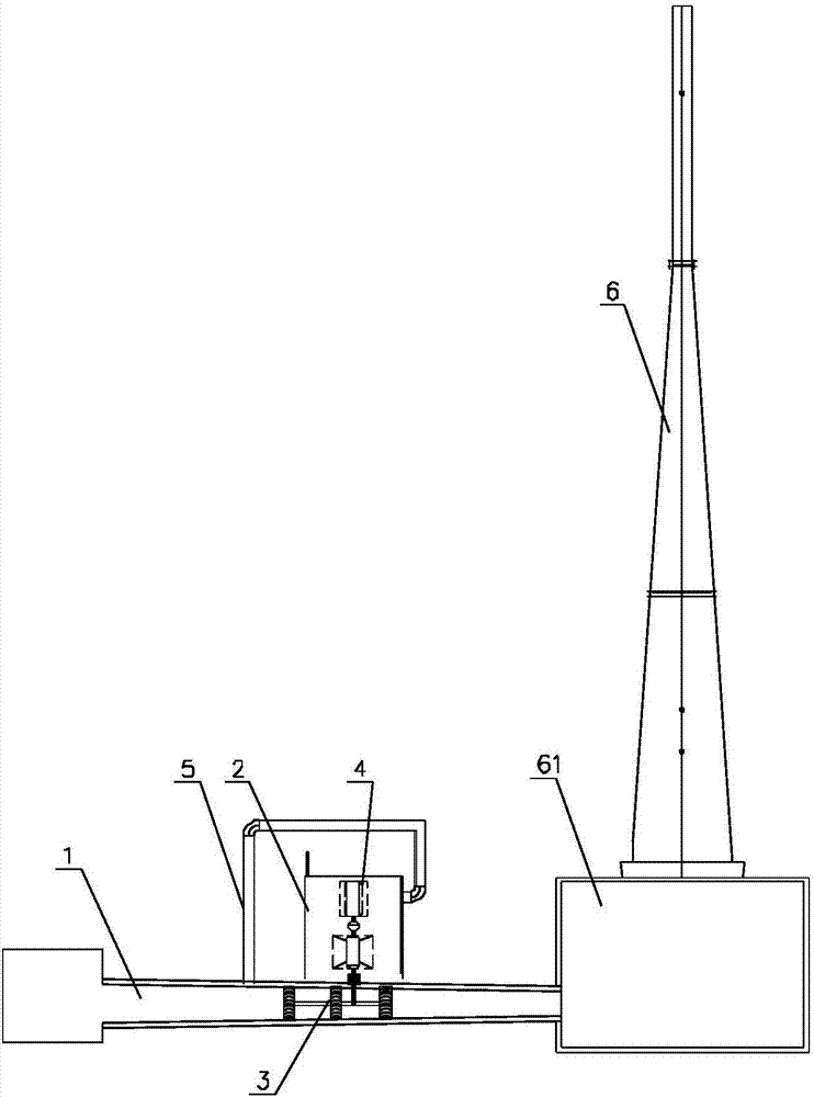
[0014] like figure 1 as shown, figure 1 It is a structural schematic diagram of a high-efficiency dust removal hot air recycling device proposed by the present invention.
[0015] refer to figure 1 , the present invention proposes a high-efficiency dust removal hot air recycling device, comprising: a hot air channel 1, a pneumatic utilization chamber 2, a pneumatic utilization mechanism, and a kinetic energy conversion mechanism 4;
[0016] The two ends of the hot air channel 1 are respectively provided with a hot air inlet and a hot air outlet. The side wall of the hot air channel 1 is provided with a gas inlet. The pneumatic utilization chamber 2 is located on the side of the hot air channel 1. an outlet, the gas outlet communicates with the gas inlet through a pipeline;
[0017] The wind utilization mechanism is provided with electrostatic adsorption blades 3, the electrostatic adsorption blades 3 are located in the hot air passage 1, the electrostatic adsorption blades 3 rotate with the flow of hot air in the hot air passage 1, and the kinetic energy conversion mechanism 4 is located in the wind utilization chamber 2, and the kinetic energy The input end of the conversion mechanism 4 is connected to the rotating shaft of the electrostatic adsorption blade 3 , and the kinetic energy conversion mechanism 4 rotates with the electrostatic adsorption blade 3 to heat the gas in the wind utilization chamber 2 .
[0018] In the specific working process of the hot air recycling device for efficient dust removal in this embodiment, the hot air flow in the hot air passage drives the electrostatic adsorption blades in the hot air passage to rotate, and the blades drive the wind utilization mechanism to utilize energy. For the dust carried, the wind uses the kinetic energy conversion mechanism in the room to rotate with the electrostatic adsorption blades, so that the wind uses the indoor gas to rotate and rub to generate heat, and the hot gas returns to the hot air channel again to bring the generated heat back to the hot air channel.
[0019] In this embodiment, the proposed high-efficiency dust-removing hot air recycling device is provided with a wind power utilization chamber on one side of the hot wind passage, and an air inlet and a gas outlet are arranged on the side wall of the wind power utilization chamber, and the gas outlet is connected to the The gas inlet is connected through pipelines, the electrostatic adsorption blade is located in the hot air channel, and the electrostatic adsorption blade rotates with the hot air flow in the hot air channel, and the kinetic energy conversion mechanism is located in the wind utilization room, and the kinetic energy conversion mechanism rotates with the electrostatic adsorption blade to control the wind force. Use the gas in the room for heating. The hot air recycling device with high efficiency dust removal through the above optimized design has a reasonable structural design. The wind utilization mechanism utilizes the kinetic energy of the hot air in the hot air channel of the electrostatic adsorption blade, and at the same time, the electrostatic adsorption blade absorbs and filters the dust carried by the gas in the hot air channel. , thereby greatly improving the utilization efficiency of hot air, and at the same time realizing the dust removal of hot air before discharge.
[0020] In a specific embodiment, the inner diameter of the hot air channel 1 gradually decreases from the hot air inlet end to the hot air outlet end, so as to ensure the moving speed of the gas in the hot air channel, thereby improving the utilization rate of kinetic energy.
[0021] In the specific embodiment of the electrostatic adsorption blade, the rotating shaft of the electrostatic adsorption blade 3 is arranged along the extension direction of the hot air channel 1. On the one hand, when the gas moves, the rotation efficiency of the electrostatic adsorption blade is improved, and on the other hand, the air carried by the gas is increased. dust adsorption efficiency.
[0022] In order to improve the heat utilization rate of the heating gas, an insulation layer 5 is provided on the outside of the pipeline between the gas outlet and the gas inlet.
[0023] In other specific embodiments, a plurality of electrostatic adsorption blades 3 are arranged in the hot air passage 1, and the plurality of electrostatic adsorption blades 3 are distributed along the extending direction of the hot air passage 1, so as to improve energy utilization efficiency and dust adsorption effect.
[0024] In order to ensure the fluidity of the gas in the hot air channel, in a further specific embodiment, it also includes an air induction tower 6, the top of the air induction tower 6 is provided with an air outlet and the bottom is provided with an air inlet, and the air inlet communicates with the hot air outlet A vertically extending air induction channel is formed between the air outlet and the air inlet, and a dust collection chamber 61 is provided at the bottom of the air induction passage to prolong the residence time of the gas in the dust collection chamber and further improve the dust removal effect.
[0025] The above is only a preferred embodiment of the present invention, but the scope of protection of the present invention is not limited thereto, any person familiar with the technical field within the technical scope disclosed in the present invention, according to the technical solution of the present invention Any equivalent replacement or change of the inventive concepts thereof shall fall within the protection scope of the present invention.

PUM

no PUM

Description & Claims & Application Information

We can also present the details of the Description, Claims and Application information to help users get a comprehensive understanding of the technical details of the patent, such as background art, summary of invention, brief description of drawings, description of embodiments, and other original content. On the other hand, users can also determine the specific scope of protection of the technology through the list of claims; as well as understand the changes in the life cycle of the technology with the presentation of the patent timeline. Login to view more.

Similar technology patents

Aggregate screening device for buildings

Owner:SHENZHEN SHENGTENG ENTERPRISE MANAGEMENT CO LTD

Draw-bar box with external article placing groove

PendingCN107212547AReasonable structural design
Owner:ZHEJIANG HONGYI CASES & LEATHER

Energy saver for base station machine room air conditioners

ActiveCN101943453AReasonable structural designSolve the problem of high power consumption
Owner:亿宏技术有限公司

Classification and recommendation of technical efficacy words

  • Reasonable structural design

Bolt machining all-in-one machine

Owner:ANHUI LIUFANG ZHONGLIAN MECHANICAL SHARE

Automatic operation device of upper drill floor and lower drill floor of drill rod

InactiveCN102230364AReasonable structural designEasy and reliable operation
Owner:SHENGLI OIL FIELD HAISHENG ENVIRONMENTAL PROTECTION ENG

High-precision vertical type machining center

ActiveCN104802038AReasonable structural designImprove rigidity and stability
Owner:普锐米勒机床(东莞)有限公司
Why Eureka
Try Eureka