
Method for determining tool changing of tool

A tool and cutting force technology, applied in the field of tool change judgment, can solve the problems of model reliability and poor economy, and achieve high economic effect

Active Publication Date: 2017-12-22
NANJING UNIV OF AERONAUTICS & ASTRONAUTICS
View PDF5 Cites 10 Cited by
  • Summary
  • Abstract
  • Description
  • Claims
  • Application Information

AI Technical Summary

Problems solved by technology

[0003] However, the existing patents on tool monitoring rely on objective experimental data, which leads to poor reliability and economy of the trained model

Method used


Image

  • Method for determining tool changing of tool
  • Method for determining tool changing of tool
  • Method for determining tool changing of tool

Examples


Embodiment Construction

[0021] The present invention will be further described below in conjunction with the accompanying drawings.

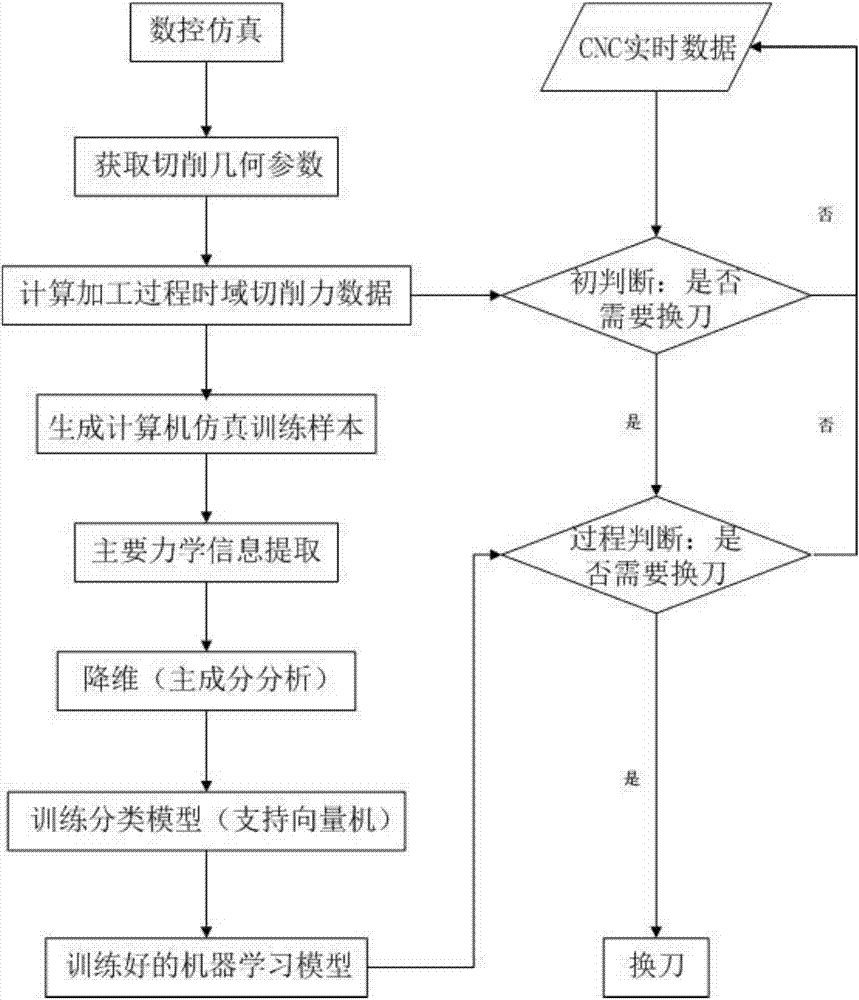
[0022] The judging method for tool change of the present invention comprises the following steps:

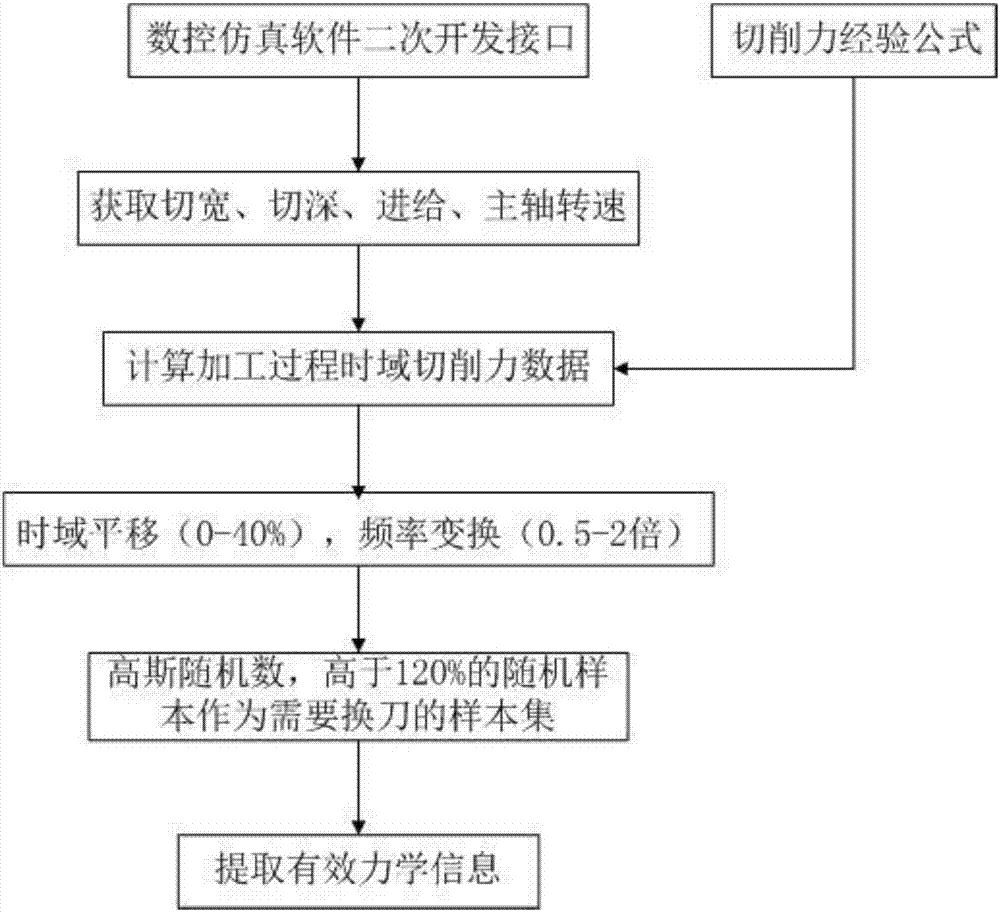
[0023] Step 1: NC simulation, obtain the cutting geometric parameters, and substitute them into the empirical formula log(F c / b)=log(k c1,1 )+(1-m c ) × logh, to obtain the time-domain cutting force data during the calculation process, and to generate computer simulation training samples based on this;

[0024] Step 2: Reduce the dimension of the sample, train the support vector machine classification model with Gaussian kernel, set the sensor to collect the cutting force signal in real time and compare it with the model. When the relative error is greater than 20%, it is judged that the tool needs to be changed.

[0025] Among them, the specific method of step 1 is as follows:

[0026] (1). Numerical control simulation: Take Vericut software as an example, set the ...


PUM


Abstract

The invention, which belongs to the technical field of mechanical manufacturing tool state monitoring, discloses a method for determining tool changing of a tool. In the prior art, wearing of a tool during the actual production process affects the processing quality of a workpiece greatly; and the efficiency of the traditional tool monitoring way is low. However, according to the method provided by the invention, the working state of the tool is reflected visually by a cutting force; and the study on the relevant calculation method is mature. On the basis of geometric simulation of the tool, calculation is carried out by using a corrected cutting force empirical formula to obtain a cutting force sample; and a sample is placed into a machine learning frame and a training result can be applied to actual processing. The method can be applied to various cutting processes and has the great significance in promoting intelligent realization of the manufacturing industry.

Description

Technical field: [0001] The invention relates to a tool change judgment method, which belongs to the technical field of machine tool monitoring. Background technique: [0002] With the increasing requirements for manufacturing automation and intelligence under Industry 4.0, the demand for automatic tool monitoring technology is also gradually increasing, and a certain number of related patents have been obtained. Patent of Huazhong University of Science and Technology, "A Method for Recognition of Tool Wear State in CNC Machine Tool Cutting Processing", which measures multi-physical quantities under tool wear state, performs wavelet packet decomposition and feature extraction on samples, and substitutes them into generalized hidden Markov initial model training ;Patent of Huazhong University of Science and Technology, "A Method for Monitoring Tool Breakage in CNC Machine Tool Milling", which monitors the three-phase current signal of the spindle motor online, performs singul...

Claims


Application Information

Patent Timeline
IPC IPC(8): G05B17/02
CPCG05B17/02
Inventor 杨吟飞李亮徐涛何宁赵威郝秀清赵国龙
Owner NANJING UNIV OF AERONAUTICS & ASTRONAUTICS
Learn More