
Multi-magnetic-circuit phase shifting transformer

A technology of phase-shifting transformers and multi-magnetic circuits, applied in transformer/inductor cores, transformer/inductor components, transformer/inductor coils/windings/connections, etc., which can solve harmonic interference, troublesome operation, and DC bias and other problems, to achieve the effect of suppressing DC bias and harmonic interference, simple design and adjustment, and improving the impact

Pending Publication Date: 2017-12-22
王奉瑾
View PDF0 Cites 1 Cited by
  • Summary
  • Abstract
  • Description
  • Claims
  • Application Information

AI Technical Summary

Problems solved by technology

In addition, the iron core design of the existing transformer (single iron core for each phase) is prone to magnetic flux leakage, DC bias, and harmonic interference, which affects the efficiency and stability of the power grid; and the current phase adjustment technology in the existing design is complex and difficult to operate Trouble, urgent need to find a simple and convenient multi-phase solution

Method used


Image

  • Multi-magnetic-circuit phase shifting transformer
  • Multi-magnetic-circuit phase shifting transformer
  • Multi-magnetic-circuit phase shifting transformer

Examples


Embodiment Construction

[0013] The patent solution is further described in conjunction with the accompanying drawings as follows:

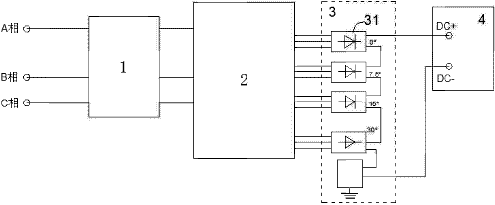
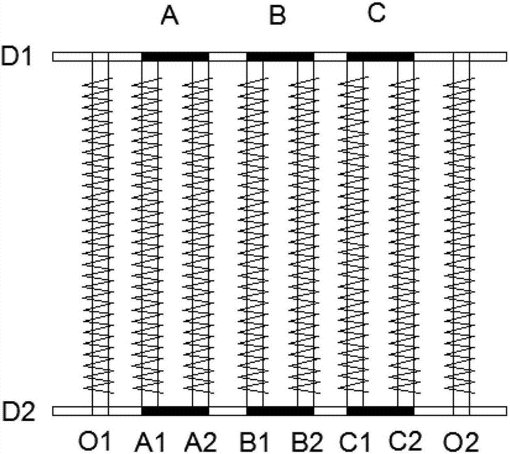
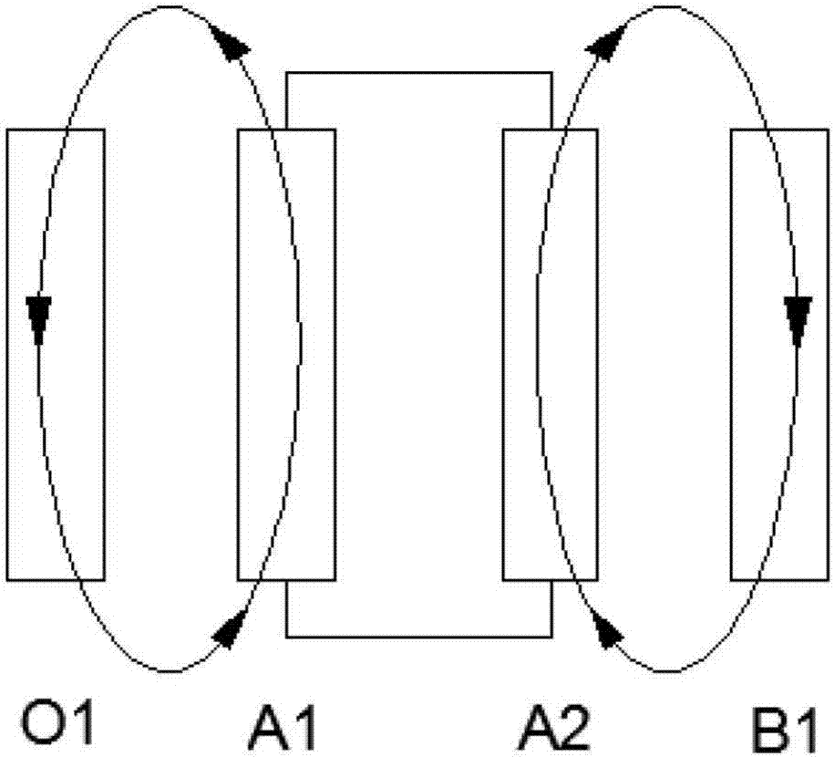
[0014] See attached figure 1 and 2 , a multi-magnetic circuit phase-shifting transformer, including an input part 1, a transformer part 2, a rectifier part 3 and an output part 4. The transformer part includes an upper jaw D1 and a lower jaw D2, and several intermediate irons arranged between them Cores, specifically including A1, A2, B1, B2, C1, C2, these intermediate iron cores are arranged in groups of two, including the first group of iron cores (A1, A2) corresponding to phase A, the second group of iron cores corresponding to phase B One group of iron cores (B1, B2) and the third group of iron cores (C1, C2) corresponding to phase C, each group is equipped with an input winding and at least one output winding, the input winding and output winding are respectively in the shape of "8" "Winning in the direction of the font, side yoke iron cores O1 and O2 are also arr...


PUM


Abstract

The invention discloses a multi-magnetic-circuit phase shifting transformer which comprises an input part, a voltage transformation part, a rectification part and an output part, wherein the voltage transformation part comprises an upper jaw and a lower jaw, as well as multiple intermediate iron cores disposed between the upper jaw and the lower jaw; the intermediate iron cores are arranged in paired groups; each group is correspondingly sleeved by an input winding and at least one output winding; the input winding and the output winding are wound in a "8" shaped pattern; side yoke iron cores are disposed beside the intermediate iron cores located on the left outmost side and the right outmost side; the output winding comprises an upper tap, a lower tap and at least one middle tap; and current phase shifting is achieved through wiring modes of the taps of the output winding. According to the invention, magnetic circuits are formed between the iron cores of each phase and the adjacent iron cores, so magnetic flux leakage can be minimized; direct current magnetic bias and harmonic interference in transformer circuits can be oppressed; and the current phase shifting is achieved by the wiring modes of the taps of the output winding, so current phases can be designed and adjusted easily.

Description

technical field [0001] The invention belongs to the technical field of power equipment, and in particular relates to a multi-magnetic circuit phase-shifting transformer. Background technique [0002] As the power of switching power supply equipment increases, its impact on the overall grid and electrical equipment in the grid is also increasing, causing serious harmonic pollution in the grid. For high-power occasions of tens or even hundreds of kilowatts, the existing multi-pulse rectification technology is generally used to suppress or offset certain harmonics of specific orders in the input current. In addition, the iron core design of the existing transformer (single iron core for each phase) is prone to magnetic flux leakage, DC bias, and harmonic interference, which affects the efficiency and stability of the power grid; and the current phase adjustment technology in the existing design is complex and difficult to operate Trouble, it is urgent to find a simple and conv...

Claims


Application Information

Patent Timeline
Patent Type & Authority Applications(China)
IPC IPC(8): H01F27/34H01F27/29H01F27/24H01F27/30H01F27/28H01F27/40
CPCH01F27/24H01F27/28H01F27/29H01F27/306H01F27/34H01F27/346H01F27/40
Inventor 王奉瑾戴雪青
Owner 王奉瑾
Learn More