Single-sided light-emitting CSP light source and manufacturing method thereof

A technology of single-sided light emitting and manufacturing methods, which is applied in the direction of electrical components, electric solid devices, circuits, etc., can solve the problems of reducing the reliability, safety, brightness of the light source, and shortening the life of the light source, so as to avoid side and bottom surface The effect of emitting light, concentrating light, and improving light efficiency

Active Publication Date: 2017-12-22
江西省兆驰光电有限公司
View PDF4 Cites 8 Cited by
  • Summary
  • Abstract
  • Description
  • Claims
  • Application Information

AI Technical Summary

Problems solved by technology

The white glue 101 of the single-sided CSP light source in the prior art blocks the side light emission of the light-emitting chip 103, and the brightness of the light source is reduced; at the same time, because the white glue 101 blocks the side light emission of the light-emitting chip 103, the light is reflected and refracted multiple times. The process light is converted into heat, which greatly increases the calorific value, reduces the reliability and safety of the light source, and shortens the life of the light source

Method used


Image

  • Single-sided light-emitting CSP light source and manufacturing method thereof
  • Single-sided light-emitting CSP light source and manufacturing method thereof
  • Single-sided light-emitting CSP light source and manufacturing method thereof

Examples


Embodiment Construction

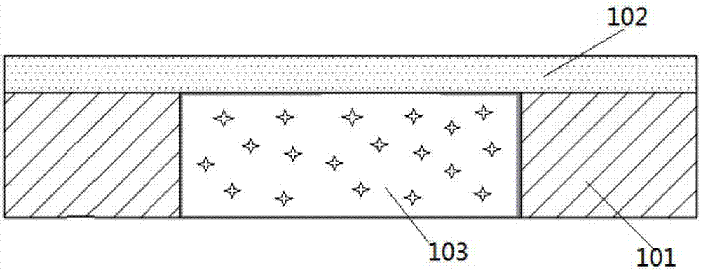
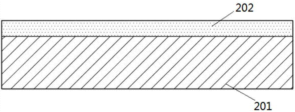
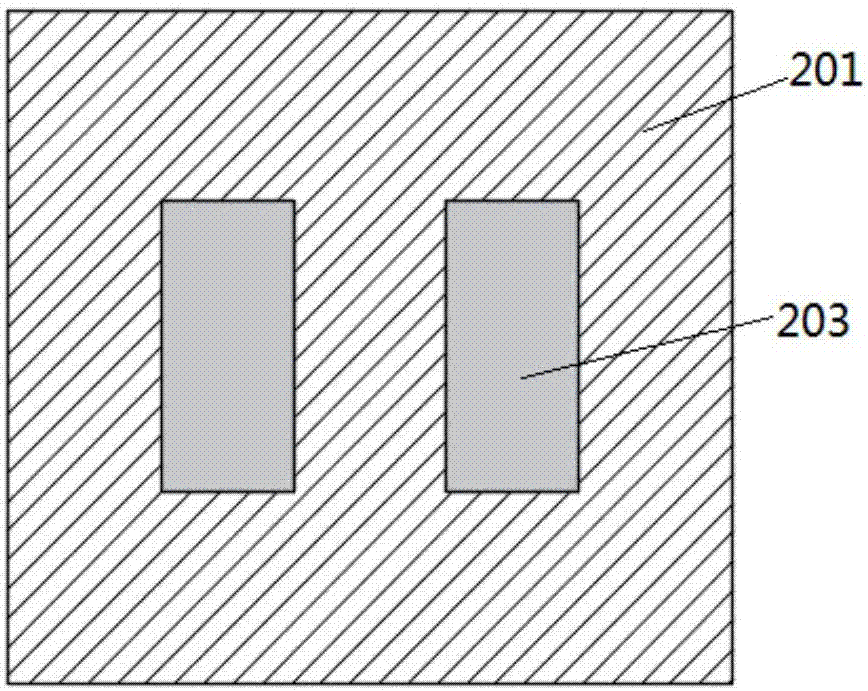
[0048] See Figure 2~4 The single-sided light-emitting CSP light source of the present invention includes a light-emitting chip 204, a fluorescent glue layer 202, a transparent glue layer 205, and a white glue layer 201. The light-emitting chip 204 is located directly below the fluorescent glue layer 202, and the transparent glue layer 204 is disposed At the periphery of the light-emitting chip 204, it is adjacent to the periphery of the light-emitting chip 204 and connected to the upper fluorescent glue layer 202. The white glue layer 201 is located on the periphery of the light-transmitting glue layer 205 and connected to the upper fluorescent glue layer 202. The light-emitting chip 204 is transparent The upper surface of the glue layer 205 and the white glue layer 201 are both connected to the lower surface of the fluorescent glue layer 202. In this way, the overall structure is compact and the light emitting effect is good. The fluorescent glue layer 202 is close to the ligh...


PUM


Abstract

The invention discloses a single-sided light-emitting CSP light source, which comprises a light-emitting chip, a fluorescent glue layer, a light-transmitting glue layer and a white glue layer. The light-emitting chip is arranged under the fluorescent glue layer. The light-transmitting glue layer is arranged on the periphery of the light-emitting chip, and has a wide upper part and a narrow lower part. The white glue layer is arranged on the periphery of the light-transmitting glue layer. An interface of the light-transmitting glue layer and the white glue layer forms a tilt included angle with the side surface of the light-emitting chip. The manufacturing method of the single-sided light-emitting CSP light source comprises the steps of: arranging a fluorescent film on a substrate; arranging light-transmitting glue and light emitting chips in the middle of the light-transmitting glue on the fluorescent film; covering a separation film; placing an isolation mould between every two adjacent light-emitting chips to form a cavity, so that the light-transmitting glue is extruded into the cavity and cured; removing the isolation moulds and the separation film; filling white glue; and cutting the white glue to obtain the single-sided light-emitting CSP light source. The single-sided light-emitting CSP light source can reflect light of the light-emitting chips to the fluorescent glue layer and an emergent surface, prevents light from emitting from the lateral and bottom surfaces, and improves the utilization rate of light energy. The manufacturing method of the single-sided light-emitting CSP light source has the advantages of simple operation, simple steps, simple tools and low manufacturing cost.

Description

【Technical Field】 [0001] The present invention relates to the technical field of LEDs, in particular to a single-sided luminous CSP light source and a manufacturing method thereof. 【Background technique】 [0002] The conventional single-sided light-emitting CSP (Chip Scale Package) light source structure in the prior art, such as figure 1 As shown, it is composed of a light-emitting chip 103 in the center, a white glue 101 surrounding the light-emitting chip 103, and a fluorescent layer 102 on the upper side; among them, the light-emitting chip 103 is a light-emitting chip with an electrode located at the bottom of the light-emitting chip, and the bonding wire can be omitted. In the process, the CSP directly solders the light source on the substrate through solder; the phosphor layer 102 is made of a mixture of transparent silica gel, phosphor powder and auxiliary additives. The manufacturing method of the common single-sided CSP light source is to arrange the light-emitting chip...

Claims


Application Information

Patent Timeline
Patent Type & Authority Applications(China)
IPC IPC(8): H01L33/48H01L33/52H01L33/60H01L33/00
CPCH01L33/005H01L33/48H01L33/52H01L33/60H01L2224/96
Inventor 周波何至年陈凭
Owner 江西省兆驰光电有限公司
Why Eureka
Try Eureka