Distributed smart energy sharing system

An energy system and distributed technology, applied in transmission systems, information technology support systems, coin-operated equipment for distributing discrete items, etc., can solve problems such as single energy sharing methods

Pending Publication Date: 2017-12-22
ZHEJIANG LUTE ENERGY TECH
View PDF1 Cites 0 Cited by
  • Summary
  • Abstract
  • Description
  • Claims
  • Application Information

AI Technical Summary

Problems solved by technology

[0004] Although the above-mentioned solution solves the problems existing in the existing technology to a certain extent, the solution still exists: the energy sharing method is single, and only electric vehicle batteries can be shared.

Method used


Image

  • Distributed smart energy sharing system
  • Distributed smart energy sharing system
  • Distributed smart energy sharing system

Examples


Embodiment 1

[0028] This embodiment belongs to the general mode.

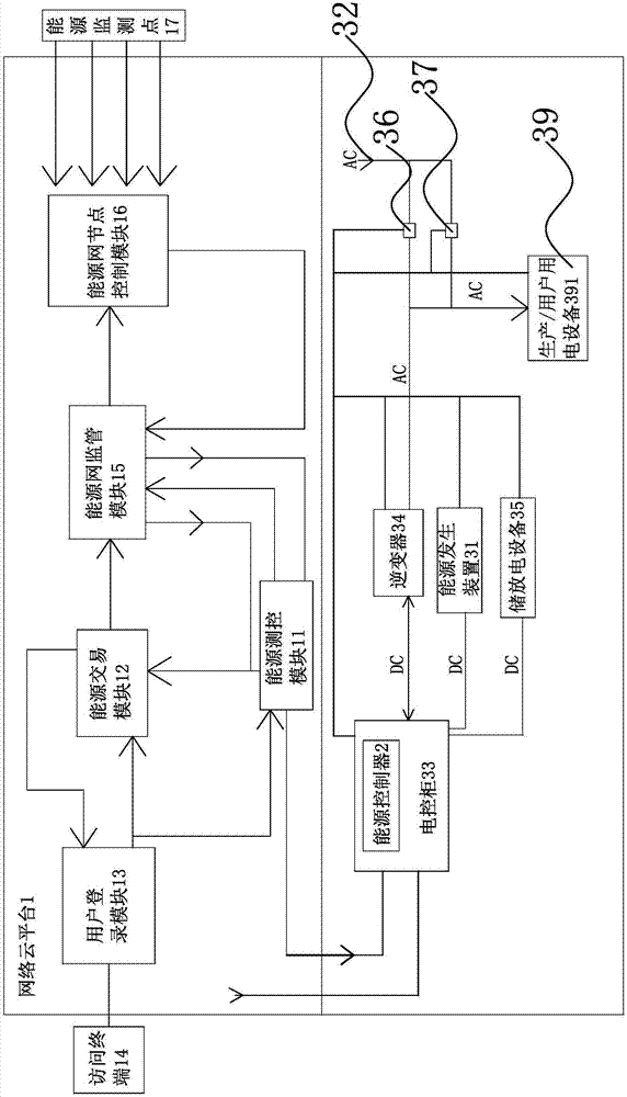
[0029] Such as figure 2 As shown, the distributed intelligent shared energy system includes a network cloud platform 1, the network cloud platform 1 is connected to at least one energy controller 2, the energy controller 2 is connected to an energy generating device 31, and the energy generating device 31 is connected to an external energy network 32 connected;

[0030] Wherein, the energy controller 2 is configured to be able to sell at least a part of the energy generated by the energy generating device 31 through the network cloud platform 1, and to be able to buy energy from the external energy network 32 through the network cloud platform 1;

[0031] The network cloud platform 1 is configured to increase the amount corresponding to the account to which the energy controller 2 belongs according to the amount of energy sold, and to decrease the amount corresponding to the account to which the energy controller 2 belong...

Embodiment 2

[0045] The structure, principle and implementation steps of this embodiment are similar to Embodiment 1, the difference lies in:

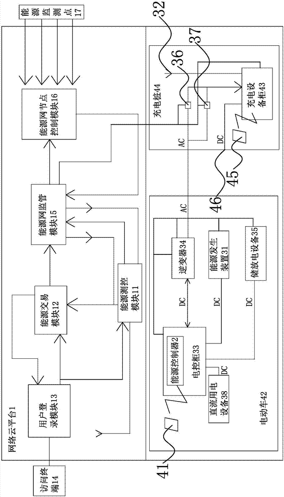
[0046] This embodiment belongs to the operation mode of electric vehicle 42 sharing distributed energy.

[0047] Such as image 3 As shown, the energy controller 2 also includes a first identification module 41 connected to the CPU module 21, the DC power equipment 38 is a motor, the DC generator is a human power generation device, the electric control cabinet 33, the inverter 34, and the DC generator The device, the storage and discharge equipment 35 and the electric motor are all arranged on the electric vehicle 42, and the electric motor is used to drive the electric vehicle 42 to rotate. The electric energy metering device 36 for selling and the electric energy metering device 37 for buying are all connected to the external power grid through the charging equipment cabinet 43, charging The equipment cabinet 43, the sold electric energy meterin...

Embodiment 3

[0051] The structure, principle and implementation steps of this embodiment are similar to Embodiment 1, the difference lies in:

[0052] This embodiment belongs to the multi-energy complementary smart energy operation mode.

[0053] Such as Figure 4 As shown, the electric control cabinet 33, the inverter 34, the direct current generating device, the storage and discharge equipment 35, the alternating current power consumption equipment 39, the selling electric energy metering device 36 and the buying electric energy metering device 37 are all connected to the equipment controller 51, and the selling Both the outgoing electric energy metering device 36 and the incoming electric energy metering device 37 are connected to the electric control cabinet 33 ; the AC power consumption equipment 39 includes production / user power consumption equipment 391 .

[0054] The cloud network platform cooperates with the device controller 51 to realize technological / procedural / functional inte...


PUM


Abstract

The invention provides a distributed smart energy sharing system, solving the technical problem that the prior art cannot realize energy sharing. The distributed smart energy sharing system includes a network cloud platform, wherein the network cloud platform is connected with at least energy controller; the energy controller is connected with an energy generating device; and the energy generating device is connected with an external energy network. The distributed smart energy sharing system has the advantages that 1) according to identity/location/settlement/transaction information, according to the protocol mode, generation/storage/power supply equipment at the site completes control of flowing direction and flowing of energy, thus realizing energy sharing; 2) when power storage/discharge equipment is in the non self-used state, the distributed smart energy sharing system provides convenience for sharing of electric energy for other users in the power network, and offers assistance for peak valley adjusting of the power network and distribution balance of lines, and at the same time, is conductive to manpower electricity generation, and energy conservation and environment protection; and 3) the cloud network platform is coordinated with an equipment controller to realize smart operation control on the local equipment remotely or on the site.

Description

technical field [0001] The invention belongs to the field of shared energy systems, and in particular relates to a distributed intelligent shared energy system. Background technique [0002] The traditional on-site / remote energy-related / heat automatic control system device uses energy-related equipment as the controlled equipment, and mainly performs functional process / operating process parameter adjustment control / start-stop control / sequence control / chain control / security alarm control . At present, energy-saving control for the purpose of saving energy is the main form, but does not include active control of energy creation and transfer transactions, and energy sharing has not been realized. [0003] In order to solve the problems existing in the prior art, people have carried out long-term exploration and proposed various solutions. For example, a Chinese patent document discloses a battery energy sharing system and method for electric vehicles [application number: 2014...

Claims


Application Information

Patent Timeline
Patent Type & Authority Applications(China)
IPC IPC(8): H02J3/00G07F15/00H04L29/08
CPCH02J3/008H04L67/12G07F15/003G07F15/008Y02T90/12Y04S30/14Y02T90/167
Inventor 代伯清乔瑾瑾石磊
Owner ZHEJIANG LUTE ENERGY TECH
Why Eureka
Try Eureka