Smashing device of corn harvester

A corn harvester and crushing device technology, applied to harvesters, agricultural machinery and implements, cutters, etc., can solve the problems of large size and troublesome use, and achieve the effects of small size, flexible operation and small footprint

Pending Publication Date: 2017-12-26
禹州市宇胜机械制造有限公司
0 Cites 0 Cited by

AI-Extracted Technical Summary

Problems solved by technology

However, the existing corn harvester has a large volume, and it is very troublesome to use when the area of ​​the plot...

Abstract

The invention provides a crushing device for a corn harvester, which is suitable for a corn harvester, the corn harvester includes a crushing device, an ear harvesting device, a scion device and a transmission device, and the crushing device includes a cutter shaft and a cutter head , the cutter head is fitted on the cutter shaft, and the cutter head is evenly provided with a plurality of fixing seats along the circumferential direction, and a blade is arranged on each of the fixing seats, and the second sprocket is arranged on the cutter shaft; The fringe device includes a movable auger, a fixed auger, a guide cover and a dial wheel. One end of the movable auger and the fixed auger are all arranged on the fixed plate, and the other ends are respectively arranged on both sides of the bracket, and are arranged on the fixed auger. The dial is provided with lugs on the bracket connected with the movable auger, and long holes are arranged on the auger, and the movable auger is arranged on the long holes through bolts. The equipment of the present invention is small in size, flexible in operation, and occupies a small area, and is especially suitable for occasions where large-scale equipment cannot be used, such as hilly and mountainous areas.

Application Domain

Mowers

Technology Topic

SprocketEngineering +1

Image

  • Smashing device of corn harvester
  • Smashing device of corn harvester
  • Smashing device of corn harvester

Examples

  • Experimental program(1)

Example Embodiment

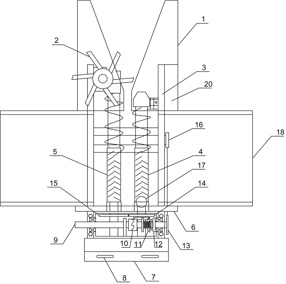
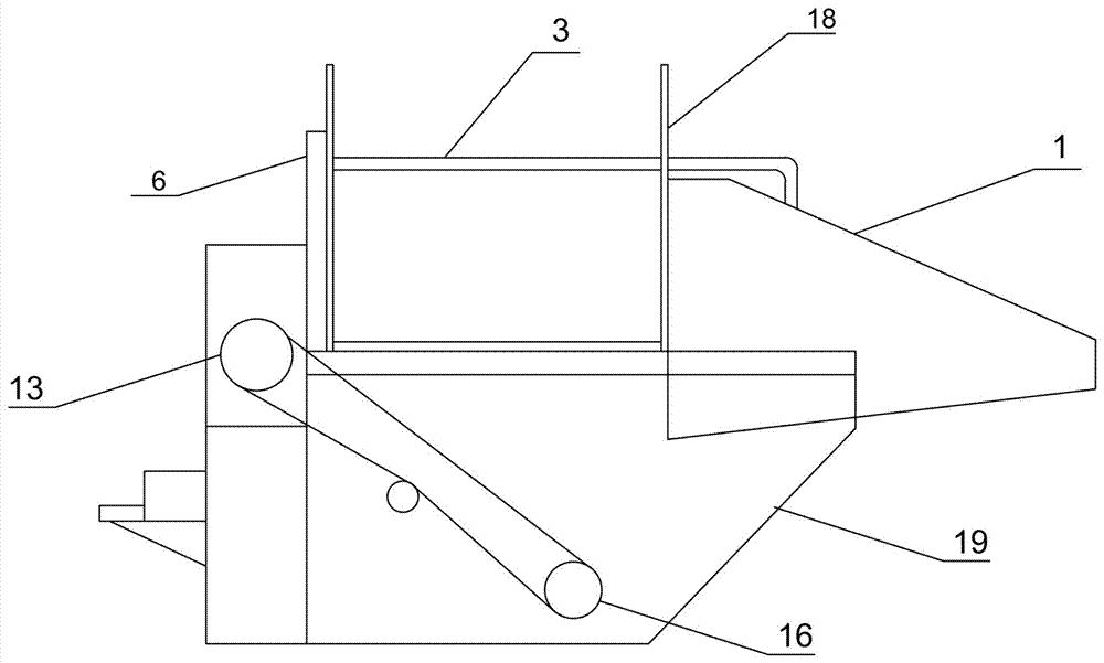
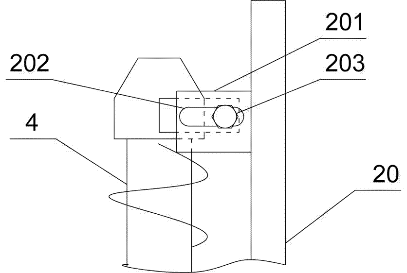
[0016] Such as Figure 1-Figure 4 As shown, the present invention provides a corn harvester, which includes a crushing device, a harvesting device, a scion device and a transmission device. The transmission device includes a gear box. A main shaft 9, a transmission shaft, a bevel gear 11, a first gear 12, a second gear 14, a third gear 15 and a fourth gear are arranged in the gear box. A first sprocket 13 is arranged on the outer side wall of the gear box. , One end of the main shaft 9 is connected with the power unit of the tractor, the other end of the main shaft 9 is provided with a clutch 10, a first gear 12 and a first sprocket 13, the transmission shaft is arranged directly below the main shaft 9, and the transmission shaft is provided with the first gear 12 The fourth gear meshed, the bevel gear 11 includes a first bevel gear and a second bevel gear, the fourth gear meshes with the first bevel gear, the first bevel gear meshes with the second bevel gear, and the second bevel gear meshes with the second gear 14 Coaxially, the second gear 14 meshes with the third gear 15; the first sprocket 13 and the second sprocket 16 are driven by a chain. The second sprocket 16 is arranged on the cutter shaft 211, and when the main shaft 9 rotates, the cutter shaft 211 is driven to rotate to provide power for the crushing device. The second gear 14 is coaxial with the movable auger 4, and the second gear 14 meshes with the third gear 15. The rotation of the second gear 14 drives the movable auger 4 and the fixed auger 5 to rotate.
[0017] The clutch 10 of the present invention is a clutch commonly used in the industry. In this example, 304 stainless steel with a cross-sectional diameter of 10 mm is used to make the fork shaft, and a commercially available cylindrical spiral tension spring with a diameter of 15 mm is used as the return tension spring. The mounting hole is installed on the shift fork shaft, and the reset extension spring is installed on the hanging ring of the reset extension spring.
[0018] Such as figure 1 , Figure 4 As shown, the crushing device includes a cutter shaft 211 and a cutter head 212. The cutter head 212 is sleeved on the cutter shaft 211. When the cutter shaft 211 rotates, it drives the cutter head 212 to rotate. The cutter head 212 is evenly provided with a plurality of fixed seats 213 along the circumferential direction. A blade 214 is arranged on each fixing seat 213, and the second sprocket 16 is arranged on the cutter shaft 211. When the corn harvester of the present invention is started, the knife shaft 211 drives the cutter head 212 to rotate, and the blade 214 crushes the corn stalks during the rotation. The present invention includes a plurality of blades 214, and each blade 214 is fixed on a fixed seat 213, and The blade 214 is fixed on the fixing seat 213 by the bolt 215, and the blade 214 does not need to be completely replaced when it is damaged, only the damaged blade can be replaced, which is convenient for operation and reduces maintenance costs.
[0019] Such as figure 1 , image 3 As shown, the harvesting device includes a movable auger 4, a fixed auger 5, a guide cover 1 and a dial wheel 2. One end of the movable auger 4 and the fixed auger 5 are both set on the fixed plate 6, and the fixed plate 6 is set on the bracket The other ends are respectively arranged on both sides of the bracket. A dial wheel 2 is provided on the fixed auger 5, a lug 201 is provided on the bracket 20 connected to the movable auger 4, and an elongated hole 202 is provided on the lug 201, and the movable auger 4 is arranged in the elongated hole 202 by a bolt 203 On; the movable auger 4 and the fixed plate 6 are connected by a ball corner 17, the movable auger 4 is connected with the second gear 14, and the fixed auger 5 is connected with the first gear 12. There are two connecting rods 3, including a first connecting rod and a second connecting rod; there are two guide covers 1, which are respectively arranged on the bracket at one end away from the fixed plate; one end of the first connecting rod and the second connecting rod are arranged on the fixed plate The other end is set on the guide cover.
[0020] The scion device 18 includes a receiving hopper composed of a first receiving plate, a second receiving plate, a third receiving plate and a fourth receiving plate. A connecting plate 7 is provided on one side of the gear box, and a connecting hole 8 is provided on the connecting plate 7. The connecting hole 8 is connected to the tractor, and the main shaft 9 is connected to the power unit of the tractor.
[0021] When in use, the corn harvester is hung on an agricultural vehicle such as a tractor through the connection hole 8, and the tractor is driven into the field for harvesting. The guide cover 1 and the dial 2 of the ear harvesting device will straighten and guide the corn plants in contact with Between the fixed auger 5 and the movable auger 4, the fixed auger 5 and the movable auger 4 rotate towards each other, and the corn plants are compressed by the fixed auger 5 and the movable auger 4 through the gap between the two augers. The crushing device is sent to the crushing device, and the ears of corn are picked from the corn plant and dropped into the scion device 18 because they cannot pass through the gap. The movable auger 4 is connected to the fixed plate 6 with the ball corner 17, and the movable auger 4 can be rotated. Since the other end of the movable auger 4 is fixed on the bracket 20, the position of the bolt 203 in the elongated hole 202 can be adjusted to adjust the movable auger 4 and the fixed The gap between the augers 5 is to achieve the best harvest gap, which is convenient for adjusting the stalk diameter of different corn plants.
[0022] The above descriptions are only preferred embodiments of the present invention and are not intended to limit the present invention. Any modification, equivalent replacement, improvement, etc. made within the spirit and principle of the present invention shall be included in the protection of the present invention. Within range.

PUM

no PUM

Description & Claims & Application Information

We can also present the details of the Description, Claims and Application information to help users get a comprehensive understanding of the technical details of the patent, such as background art, summary of invention, brief description of drawings, description of embodiments, and other original content. On the other hand, users can also determine the specific scope of protection of the technology through the list of claims; as well as understand the changes in the life cycle of the technology with the presentation of the patent timeline. Login to view more.

Similar technology patents

Wind generating set

InactiveCN101363407Acompact structurereduce volume
Owner:SANY ELECTRIC CO LTD

Video coding apparatus

ActiveUS20070217507A1reduce volumereduce image quality
Owner:FUJITSU LTD

Classification and recommendation of technical efficacy words

  • flexible operation
  • reduce volume

Sliding type video demanding method

InactiveCN101340559Aflexible operationThe visual effect of the screen is excellent
Owner:BEIJING THUNDERSTONE TECH CO LTD

Implant release mechanism

ActiveUS20080140178A1reduce volumereduce outer diameter
Owner:COOK MEDICAL TECH LLC

Speed reduction box for turbine fracturing

Owner:YANTAI JEREH PETROLEUM EQUIP & TECH

Miniature and Multi-Band RF Coil Design

ActiveUS20100090824A1reduce volumelong wavelength
Owner:HONG KONG APPLIED SCI & TECH RES INST

Automatic washing and dewatering combined device of rotary type mop

InactiveCN102370447Areduce volumeSimple structure
Owner:上海祥美网络科技有限公司 +1

Optical imaging system

ActiveUS20070008625A1reduce volumedeteriorate with time
Owner:SAMSUNG ELECTRONICS CO LTD
Why Eureka
Try Eureka