Control system and method for functional brain deep electric stimulation

A deep brain stimulation and functional electrical stimulation technology, applied in electrotherapy, artificial respiration, physical therapy, etc., can solve the problem of inability to achieve rehabilitation control, insufficient scalp EEG signals to determine the disease state, no obvious characteristics of EMG, etc. question

Inactive Publication Date: 2017-12-26
SUZHOU INST OF BIOMEDICAL ENG & TECH CHINESE ACADEMY OF SCI
View PDF8 Cites 5 Cited by
  • Summary
  • Abstract
  • Description
  • Claims
  • Application Information

AI Technical Summary

Problems solved by technology

A few attempts to introduce physiological parameter feedback mechanisms, such as abnormal myoelectricity, abnormal EEG and other monitoring methods to adjust parameters in a closed loop, but all have certain defects, for example, they are not suitable for motor nerve di

Method used


Image

  • Control system and method for functional brain deep electric stimulation
  • Control system and method for functional brain deep electric stimulation

Examples


Embodiment 1

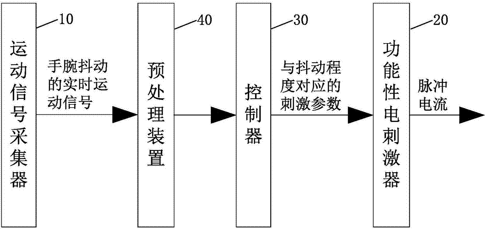
[0031] Such as figure 1 As shown, the embodiment of the present invention provides a functional deep brain stimulation control system, which includes a motion signal collector 10 , a functional electrical stimulator 20 and a controller 30 . The motion signal collector 10 is used to collect real-time motion signals of wrist shaking, and the functional electrical stimulator 20 generates pulse current for stimulation. The controller 30 is communicatively connected to the motion signal collector 10 and the functional electrical stimulator 20, respectively. The controller 30 pre-stores the shaking degree levels and the stimulation parameters corresponding to each shaking degree level, and the shaking degree levels and the stimulation parameters corresponding to each shaking degree level are preferably in the form of a scale for query. The controller 30 receives the real-time motion signal collected by the motion signal collector 10 and judges whether it belongs to the degree of sh...

Embodiment 2

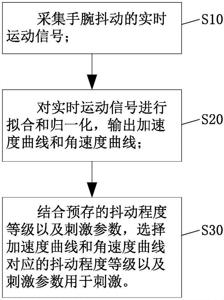
[0039] On the basis of the functional deep brain stimulation control system provided in Example 1, the embodiment of the present invention provides a functional deep brain stimulation control method, such as figure 2 As shown, it includes the following steps:

[0040] S10, collecting real-time motion signals of wrist shaking;

[0041] S20, fitting and normalizing the real-time motion signal, and outputting an acceleration curve and an angular velocity curve;

[0042] S30, combining the pre-stored shaking degree levels and stimulation parameters, selecting the shaking degree levels and stimulation parameters corresponding to the acceleration curve and the angular velocity curve for stimulation.

[0043]In the above embodiment, in step S10, it is preferable to use a watch worn on the wrist to collect real-time motion signals of wrist shaking. The real-time motion signals include three acceleration signals and three angular velocity signals in three-dimensional directions. In ...


PUM


Abstract

The invention discloses a control system and method for functional brain deep electric stimulation. The system includes a motion signal collector used for collecting real time motion signals of wrist tremble; a functional electric stimulator generating pulse current used for stimulating; a controller in communicational connection with the motion signal collector and the functional electric stimulator separately. The controller stores tremble levels and stimulation parameters corresponding to each tremble level in advance. The controller receives the real time motion signals and judges whether the motion belongs to the tremble levels or not. If the motion belongs to the tremble levels, the controller selects the stimulation parameters corresponding to the corresponding tremble level and sends the stimulation parameters to the functional electric stimulator for stimulating. According to the invention, current attack level is quantified and real time self-adaptive control is performed on functional brain deep electric stimulation. The system and method are especially suitable for real time monitoring of hand tremble of Parkinson disease sufferers and performing self-adaptive control.

Description

technical field [0001] The present invention relates to the technical field of functional deep brain stimulation, and more specifically, the present invention relates to a functional deep brain stimulation control system and method. Background technique [0002] Most of the current commercial and clinical functional deep brain stimulation control systems are designed by the open-loop control system method, that is, the current patient's onset or recovery status can only be judged by scoring the Unified Parkinson's Disease Rating Scale (UPDRS) , and adjust the electrical stimulation parameters according to the doctor's experience, including parameters such as voltage amplitude, voltage frequency, voltage pulse width, and stimulation duration. A few attempts to introduce physiological parameter feedback mechanisms, such as abnormal myoelectricity, abnormal EEG and other monitoring methods to adjust parameters in a closed loop, but all have certain defects, for example, they ar...

Claims


Application Information

Patent Timeline
IPC IPC(8): A61N1/36
CPCA61N1/36067A61N1/36139
Inventor 张云鹏陈晓禾
Owner SUZHOU INST OF BIOMEDICAL ENG & TECH CHINESE ACADEMY OF SCI
Why Eureka
Try Eureka