Full-automatic high-speed coil type wire winding machine

A winding machine, fully automatic technology, applied in the direction of conveying filamentous materials, thin material processing, transportation and packaging, etc., can solve the unsatisfactory production needs, long response time of the cylinder action, and low working efficiency of the coiler etc. to achieve the effect of saving time, shortening action time and simple structure

Active Publication Date: 2017-12-26
JIANGSU SINGCHEER MACHINERY
View PDF9 Cites 2 Cited by
  • Summary
  • Abstract
  • Description
  • Claims
  • Application Information

AI Technical Summary

Problems solved by technology

[0002] In the cable production process, it is necessary to use a coiling machine to wrap the cable in circles, but the existing coiling machine has low working efficiency and cannot meet the production needs. It is mainly manifested in the following conveniences: 1. After the wire coil is wound, the wire should be clamped, and the wire should be moved to the winding mechanism after the wire cup is cut off to wind the next wire coil
At present, the traditional method is to clamp the wires through the wire clamping device and transfer the wires to the coiling head from the wire guide rod to wind the next wire coil. It is affected by the wire diameter of the wire and cable and the position of the wire and cable at the end of the roll. It is often necessary to add a wire catching device before clamping the wire to limit the position of the wire and cable so that the clamping device can clamp it. This method affects the working efficiency of the equipment during the clamping process; 2. In the clamping air circuit control, The traditional three-position five-way solenoid valve with a closed center position can stop the cylinder in motion, but the gas in the intermediate pipeline from the cylinder to the solenoid valve is not cut off, and the control loop is long. Due to the compressibility of the air, the control It is not stable; 3. The thread trimming device used in the existing coiling equipment is simply driven by a cylinder. Because the gas has the characteristics of compression and contraction, the response time of the cylinder action is relatively long
And the existing thread trimming device has only one blade action, the other is a fixed blade, and the thread trimming stroke is longer, which also affects the thread trimming efficiency and cannot meet the requirements of fast coiling; The disks are usually fixed together, and the pressure plate rises and falls together with the coiling head. The disadvantage of this is that the pressure plate can no longer press the wire coil after the coiling head rises, which affects the beauty of the coiling effect. More importantly, it may Will cause the operation of the next process to fail

Method used


Image

  • Full-automatic high-speed coil type wire winding machine
  • Full-automatic high-speed coil type wire winding machine
  • Full-automatic high-speed coil type wire winding machine

Examples


Embodiment Construction

[0029] The technical solutions provided by the present invention will be described in detail below in conjunction with specific examples. It should be understood that the following specific embodiments are only used to illustrate the present invention and are not intended to limit the scope of the present invention.

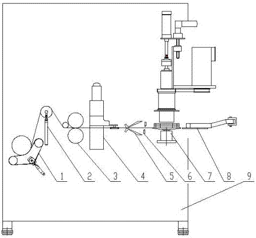
[0030] Such as figure 1 A fully automatic high-speed coiling and winding machine shown includes a frame 9 on which a wire transmission mechanism, a tension mechanism 1, a meter counter 3, a positioning device 4, and a fast clamping wire are arranged. Device 5, thread cutting device 6, mechanical gripper 8 and coiling device 7. Wherein the tension mechanism 1 adopts a magnetic powder tension device, and a buffer device 2 is arranged between the tension mechanism 1 and the meter counter 3 .

[0031] Such as Figure 5 and Figure 6 Shown is a schematic diagram of the structure of the quick clamping device 5, including a rotating base 511, wherein the rotating bas...


PUM


Abstract

The invention discloses a full-automatic high-speed coil type wire winding machine. The machine comprises a rack, wherein a wire transmission mechanism, a tensioning mechanism, a meter counter, an arranging device, a quick wire clamping device, a wire cutting device, a mechanical clamping head and a coil forming device are arranged on the rack. According to the machine, the whole production work is automatically operated under the control of PLC program, and manual interference is avoided; the machine has the characteristics of being low in working intensity of workers, and high in automation degree; the coil forming device, the wire clamping device and a wire shearing device are improved in structure, so that the acting time is greatly reduced, and as a result, the time is saved.

Description

technical field [0001] The invention relates to a wire and cable production equipment, in particular to a fully automatic high-speed coiling and winding machine. Background technique [0002] In the cable production process, it is necessary to use a coiling machine to wrap the cable in circles, but the existing coiling machine has low working efficiency and cannot meet the production needs. It is mainly manifested in the following conveniences: 1. After the wire coil is wound, the wire should be clamped, and the wire will be moved to the winding mechanism after the wire cup is cut off to wind the next wire coil. At present, the traditional method is to clamp the wires through the wire clamping device and transfer the wires to the coiling head from the wire guide rod to wind the next wire coil. It is affected by the wire diameter of the wire and cable and the position of the wire and cable at the end of the roll. It is often necessary to add a wire catching device before cla...

Claims


Application Information

Patent Timeline
Patent Type & Authority Applications(China)
IPC IPC(8): B65H54/04B65H54/52B65H54/70
CPCB65H54/04B65H54/52B65H54/70B65H2701/34
Inventor 周代烈周少林肖茂华康敏欧密
Owner JIANGSU SINGCHEER MACHINERY
Why Eureka
Try Eureka