Optical path gating mechanism

An optical path and iron core technology, applied in the field of optical path gating mechanism, can solve the problems of large power supply current and heat generation of electromagnets, and achieve the effect of small driving current and low power

Inactive Publication Date: 2017-12-26
BEIJING SDL TECH
View PDF4 Cites 0 Cited by
  • Summary
  • Abstract
  • Description
  • Claims
  • Application Information

AI Technical Summary

Problems solved by technology

When energized, the electromagnet needs to overcome the elastic force that increases linearly with ...

Method used


Image

  • Optical path gating mechanism
  • Optical path gating mechanism
  • Optical path gating mechanism

Examples


Embodiment Construction

[0024] The specific embodiments of the present invention will be described in more detail below with reference to the drawings and examples, so as to better understand the solution of the present invention and its advantages in various aspects. However, the specific embodiments and examples described below are for the purpose of illustration only, rather than limiting the present invention.

[0025] The "connection" mentioned in the present invention should be interpreted in a broad sense unless otherwise specified or limited, and may be a direct connection or a connection through an intermediary.

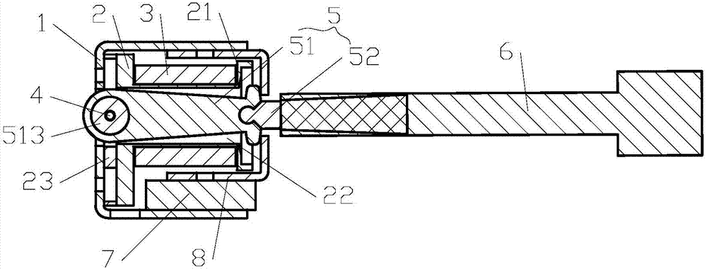
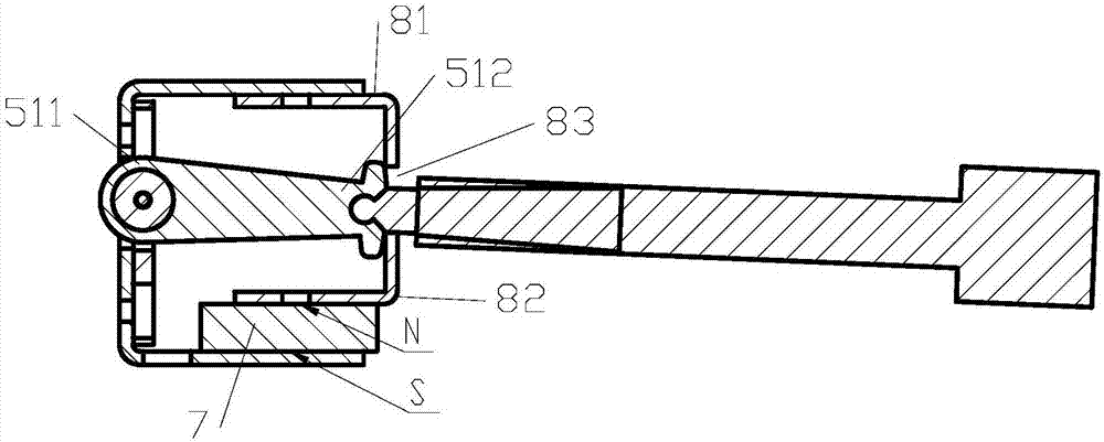
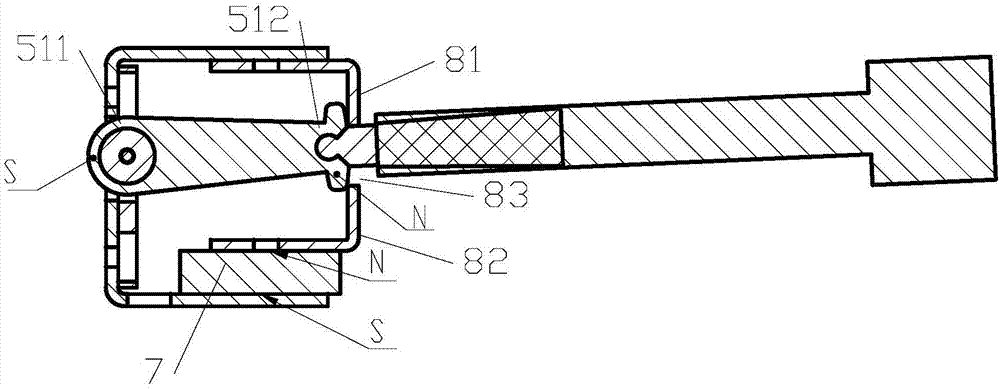
[0026] Such as figure 1 , figure 2 and image 3 As shown, the present invention provides an optical path gating mechanism, including: a housing 1 , a coil frame 2 , a coil 3 , a rotating shaft 4 , a swing arm 5 , a light blocking plate 6 , a permanent magnet 7 and a limiting plate 8 . Utilizing the cooperation of the permanent magnet and the electromagnet, the swing arm of the ...


PUM


Abstract

The invention discloses an optical path gating mechanism, which comprises a shell, a coil skeleton, a swinging arm, a permanent magnet and a limiting plate, wherein the coil skeleton is fixed in the shell, the coil groove on the outer wall of the coil skeleton is wound with a coil, the center of the coil skeleton is provided with a through iron core hole, and the bottom part of the coil skeleton is provided with a rotation shaft; an iron core swinging arm is located inside the iron core hole, the rotating end of the iron core swinging arm is arranged on the rotation shaft in a rotary mode, and an auxiliary swinging arm is fixedly connected with the swinging end of the iron core swinging arm; the permanent magnet is fixed on the shell and is located at one side of the swinging end of the iron core swinging arm; and the limiting plate is fixedly connected onto the shell, the limiting plate is provided with a swinging arm limiting hole, and the swinging arm passes through the swinging arm limiting hole to be fixedly connected with a light barrier. The optical path gating mechanism can be applied to various optical instruments, and has the advantages of low power consumption and high reliability.

Description

technical field [0001] The invention relates to the technical field of optical equipment, in particular to an optical path gating mechanism for optical equipment. Background technique [0002] Optical instruments have been widely used in industrial site testing. In industrial sites, instruments are easily affected by environmental factors such as external humidity, electromagnetic interference, temperature changes, vibrations, and floating particles. The instrument must perform regular self-checks to ensure the normal operation of the instrument. The data is accurate and reliable. [0003] For example, in the on-line monitoring equipment of laser forward scattering particle concentration, in order to regularly measure whether the mirror surface is polluted, the beam is divided into two beams of parallel light. Two beams of parallel light, one beam is used for instrument self-inspection, the other beam is used for particle measurement, and the two optical paths are combined ...

Claims


Application Information

Patent Timeline
IPC IPC(8): G02B26/02H01F7/06
CPCG02B26/02H01F7/06
Inventor 敖小强李永帅
Owner BEIJING SDL TECH
Why Eureka
Try Eureka