Film sheet used for cover plate and manufacturing method thereof

A production method and diaphragm technology are applied in the field of diaphragms for cover plates and their preparation, which can solve the problems of long coating time, high cost, and large color fluctuation range, and achieve consistency, low processing cost, and high coating quality. short time effect

Inactive Publication Date: 2017-12-26
JRD COMM (SHENZHEN) LTD
View PDF3 Cites 30 Cited by
  • Summary
  • Abstract
  • Description
  • Claims
  • Application Information

AI Technical Summary

Problems solved by technology

[0003] 1. The appearance yield is low, mainly particles and dust spots, and the coating will enlarge the particles and dust spots;
[0004] 2. The color fluctuation range of pure coating toning is relatively large;
[0005] 3. The colored optical coating process is complicated, the coating time is long, the efficiency is low, and the cost is high

Method used


Image

  • Film sheet used for cover plate and manufacturing method thereof
  • Film sheet used for cover plate and manufacturing method thereof
  • Film sheet used for cover plate and manufacturing method thereof

Examples


Embodiment 1

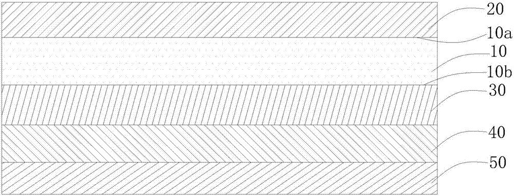
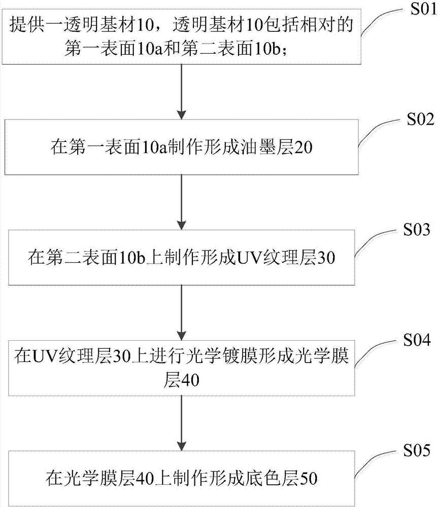
[0039] like figure 1 As shown, the film for the cover plate provided by the embodiment of the present invention includes a transparent substrate 10, an ink layer 20, a UV texture layer 30, and an optical film layer 40. The transparent substrate 10 includes a first surface 10a and a first surface On the second surface 10b opposite to 10a, the ink layer 20 is arranged on the first surface 10a, the UV texture layer 30 is arranged on the second surface 10b, and the optical film layer 40 is arranged on the UV texture layer 30, wherein the ink layer 20 is light-transmitting colored layer, and the optical film layer 40 is a reflective layer. In order to ensure the color effect of the film, a base color layer is arranged on the optical film layer 40 .

[0040] The above-mentioned ink layer 20 is pasted on the glass cover, and the ink layer can weaken the appearance defects after the optical coating, such as particles and dust spots; the simple color optical coating realizes the color...

Embodiment 2

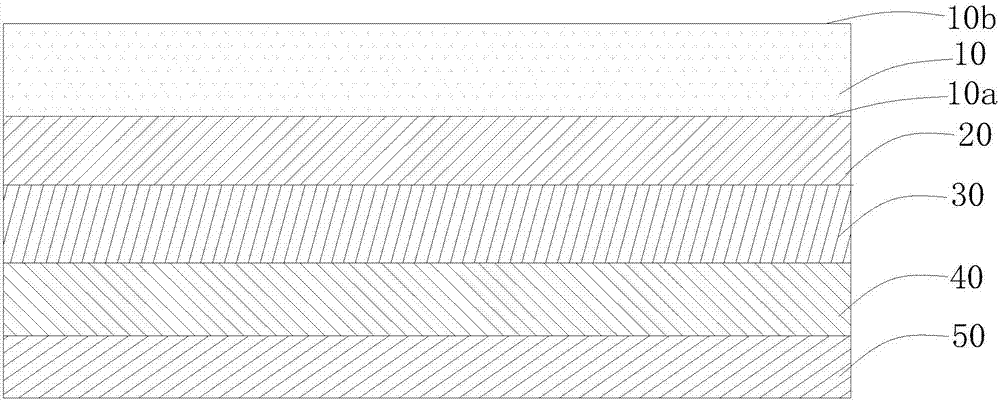
[0053] like image 3 As shown, the difference between the film of Example 2 and Example 1 is that the UV texture layer 30 is disposed on the ink layer 20, that is, the second surface 10b of the transparent substrate 10 is not treated.

[0054] Figure 4 Shows the flow chart of the diaphragm manufacturing process in this embodiment 2, wherein, step S01', step S02', step S04', step S05' are respectively the same as step S01, step S02, step S04, step S05 in embodiment 1 The same, except that in step S03 ′, the UV texture layer 30 is formed on the ink layer 20 .

[0055] After the diaphragm of the embodiment 2 is manufactured, an adhesive layer can be provided on the base color layer 50, and the diaphragm can be pasted on the plastic cover plate, so that the plastic cover plate has better color and texture effects. Of course, in other implementation manners, optical glue can be disposed on the second surface 10 b of the transparent substrate 10 to stick the film on the glass cov...


PUM

PropertyMeasurementUnit
thicknessaaaaaaaaaa
thicknessaaaaaaaaaa
thicknessaaaaaaaaaa

Abstract

The invention discloses a film sheet used for a cover plate. The film sheet comprises a transparent base material, a printing ink layer, a UV texture layer and an optical film layer. The transparent base material comprises a first surface and a second surface opposite to the first surface. The printing ink layer is arranged on the first surface. The optical film layer is arranged on the UV texture layer. The UV texture layer is arranged on the second surface or on the printing ink layer. The printing ink layer is a light-transmit colored layer. The optical film layer is a reflecting layer. The invention also discloses a manufacturing method of the film sheet used for the cover plate. A technology is simple, film coating time is short, processing cost is low, the film sheet is combined with the optical film layer through the printing ink layer so that a color difference of the film sheet can be reduced and a color can maintain consistency, and simultaneously the cover plate which is pasted with the film sheet possesses a texture effect.

Description

technical field [0001] The invention relates to the field of electronic equipment, in particular to a diaphragm used for a cover plate and a preparation method thereof. Background technique [0002] With the development of communication technology, 5G is the future development trend. 5G has higher and higher requirements for radio frequency. Due to the influence of metal all-in-one machine on the shielding of antenna radio frequency, it is bound to be covered by front and rear glass covers or rear plastic covers in the future. replaced by the structure. At present, the popular appearance decoration method of the rear glass cover or plastic cover usually adopts the bonding process of the diaphragm and the cover to achieve the texture effect. This kind of process uses colored optical coating to achieve the color effect. However, this There are following problems in this technique: [0003] 1. The appearance yield is low, mainly particles and dust spots, and the coating will ...

Claims


Application Information

Patent Timeline
Patent Type & Authority Applications(China)
IPC IPC(8): H05K5/02G02B5/23G02B5/08B41M1/12B41M1/18B41M1/26B41M1/30B41M7/00
CPCH05K5/0243B41M1/12B41M1/18B41M1/26B41M1/30B41M7/0081B41M7/009G02B5/08G02B5/23
Inventor 彭世晓曾翠霞罗海宝尹章新
Owner JRD COMM (SHENZHEN) LTD
Why Eureka
Try Eureka