Horizontal gas-solid reactor

A gas-solid reactor, horizontal reactor technology, applied in chemical instruments and methods, chemical/physical processes, etc., can solve the problem of reducing the contact area and reaction time of gas-solid phase reactants, poor control of bed temperature, and gas-solid phase reaction. It can reduce the difficulty of recycling operation, simple structure, and convenient manufacturing and maintenance.

Active Publication Date: 2017-12-29
欧中电子材料(重庆)有限公司
View PDF10 Cites 1 Cited by
  • Summary
  • Abstract
  • Description
  • Claims
  • Application Information

AI Technical Summary

Problems solved by technology

[0003] Among them, the fixed bed reactor is mainly used in the gas-solid phase catalytic reaction process, with simple structure, small volume, stable operation, easy control, and easy realization of large-scale and continuous production, but the bed temperature is not easy to control, and it is easy to "overheat" , and there are requirements on the size of the solid particles. If the particles with a small particle size are used, the fluid resistance will increase and the operation will be difficult. If the particles with a large particle size are used, the contact area of ​​the gas-solid phase reactants will be reduced. and reaction time, leading to a decrease in reaction efficiency
[0004] The fluidized bed reactor is more common in the non-catalytic gas-solid phase reaction process. It has good heat transfer effect, easy temperature control, high mass transfer and heat transfer efficiency, and large production capacity per unit of equipment. It is suitable for the production needs of large chemical industries, but it is also There are certain requirements on the size of solid particles in the reactor. If the particles are too large, the gas flow rate will be too large, resulting in poor gas-solid contact and low reaction efficiency. If the particles are too small, a large number of particles will be taken out of the reactor by the gas. , causing pipe blockage or difficulty in recycling

Method used


Image

  • Horizontal gas-solid reactor
  • Horizontal gas-solid reactor
  • Horizontal gas-solid reactor

Examples


Embodiment Construction

[0013] In order to make the purpose, technical solutions and advantages of the embodiments of the present invention clearer, the technical solutions in the embodiments of the present invention will be clearly and completely described below in conjunction with the drawings in the embodiments of the present invention. Obviously, the described embodiments It is a part of embodiments of the present invention, but not all embodiments. Based on the embodiments of the present invention, all other embodiments obtained by persons of ordinary skill in the art without making creative efforts belong to the protection scope of the present invention.

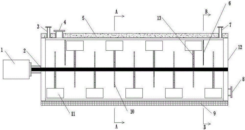
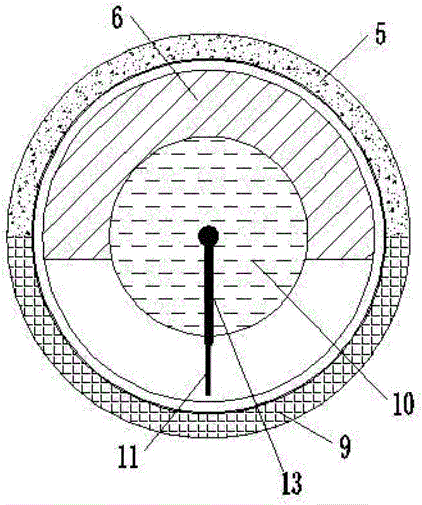
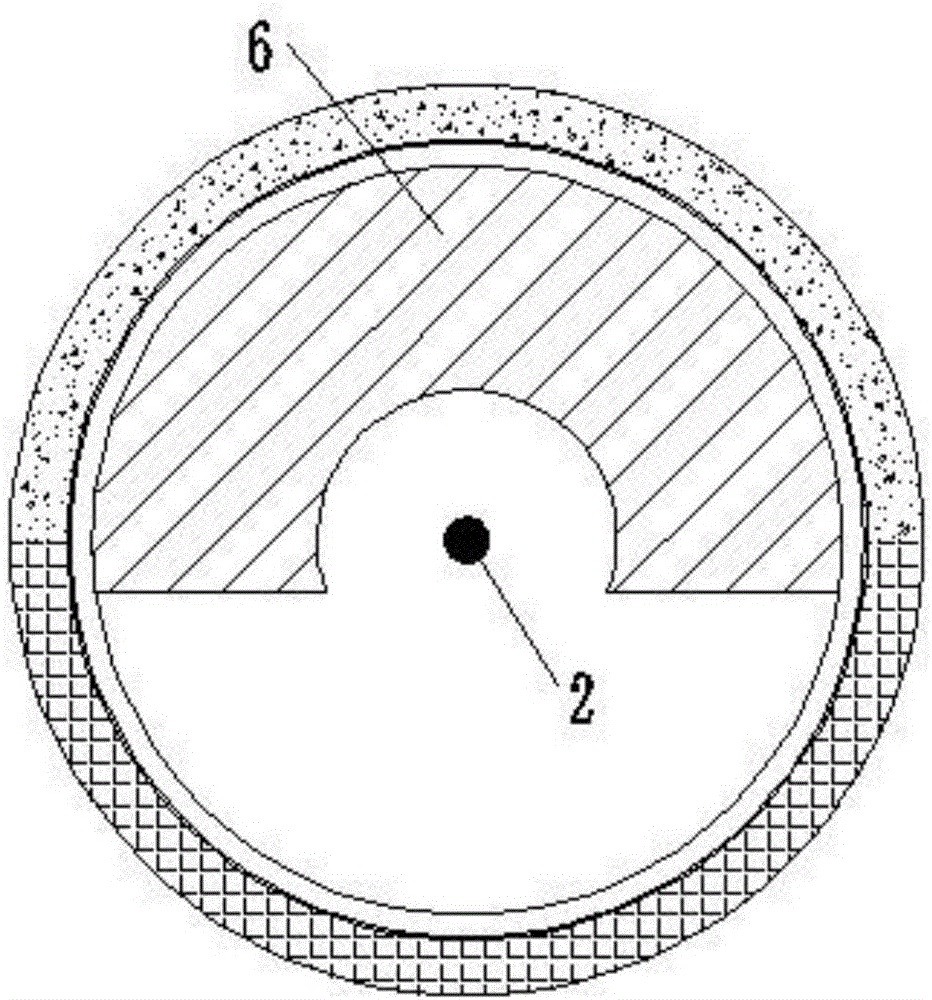
[0014] Figure 1 to Figure 3 Show the structural representation of a preferred embodiment of the present invention, a kind of horizontal gas-solid reactor in the figure, mainly is made up of horizontal reactor shell 12 and the stirring device that is arranged on its inside, in described reaction The bottom and top of the reactor cylinder 12 ...


PUM


Abstract

The invention discloses a horizontal gas-solid reactor which mainly comprises a horizontal reactor barrel and a stirring device. The stirring device is arranged inside the horizontal reactor barrel, a heating sleeve and a heat-insulation layer are arranged at the bottom and the top of the horizontal reactor barrel, the stirring device comprises a stirring motor, a stirring shaft, barriers and lifting plates, the stirring motor is arranged on the outer side of the reactor barrel, the stirring shaft which penetrates the reactor barrel can be driven by the stirring motor to rotate, the barriers are uniformly arranged on the stirring shaft at intervals, each lifting plate is fixedly connected with the front end of the corresponding barrier, the directions of the lifting plates on the adjacent barriers are opposite to one another, 180-degree angles are formed in the directions of the lifting plates on the adjacent barriers, and each barrier is connected with the corresponding lifting plate on the barrier in a cross manner at 90-degree angles. The horizontal gas-solid reactor has the advantages that the horizontal gas-solid reactor is insensitive to the particle size distribution of solid particles, is free of requirements on the flow rates of raw gas, is good in controllability in reaction procedures and is high in operational stability and safety and low in energy consumption, excellent reaction effects can be realized, and the reaction efficiency can be improved.

Description

technical field [0001] The invention relates to a reactor for chemical reaction between gas and solid, in particular to a horizontal gas-solid reactor, which belongs to the technical field of chemical equipment. Background technique [0002] At present, it is known that in chemical production, most of the gas-solid phase reactions use fluidized bed, fixed bed and other types of reactors. [0003] Among them, the fixed bed reactor is mainly used in the gas-solid phase catalytic reaction process, with simple structure, small volume, stable operation, easy control, and easy realization of large-scale and continuous production, but the bed temperature is not easy to control, and it is easy to "overheat" , and there are requirements on the size of the solid particles. If the particles with a small particle size are used, the fluid resistance will increase and the operation will be difficult. If the particles with a large particle size are used, the contact area of ​​the gas-solid...

Claims


Application Information

Patent Timeline
Patent Type & Authority Applications(China)
IPC IPC(8): B01J8/10B01J8/08
CPCB01J8/087B01J8/10B01J2208/00212B01J2208/00477B01J2208/0084B01J2208/00867
Inventor 张建长雷海平
Owner 欧中电子材料(重庆)有限公司
Why Eureka
Try Eureka