
Die-cut cylinders for die-cut substrates

A printing material and die-cutting technology, applied in printing, printing presses, rotary printing presses, etc., can solve the problems of grid width limitation, poor functional reliability and poor utilization of pages

Active Publication Date: 2021-07-20
HEIDELBERGER DRUCKMASCHINEN AG
View PDF6 Cites 0 Cited by
  • Summary
  • Abstract
  • Description
  • Claims
  • Application Information

AI Technical Summary

Problems solved by technology

[0004] On the downside, when manufacturing die-cut boards, the placement of die-cut waste is limited by the grid width of the grid of air openings
The result is poor functional reliability and sheet utilization when guiding small die-cutting waste

Method used


Image

  • Die-cut cylinders for die-cut substrates
  • Die-cut cylinders for die-cut substrates
  • Die-cut cylinders for die-cut substrates

Examples


Embodiment Construction

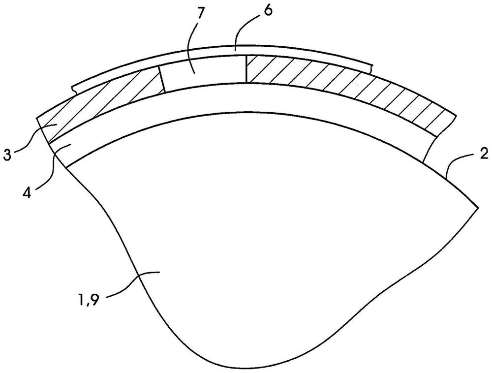
[0023] figure 1 A partial view of the die cutting roller 1 is shown. The die cutting roller 1 works with the imprint drum, and the pressurizing roller is not shown in the drawings. The die-cutting roller 1 is used to die from the printing material composed of foil or preferably paper or thick panel. The receiving material can have the shape of a web or preferred page. In the case of the piping material page, the imprinting drum has a jaw for fixed page leading edges. The die cutting roller 1 and the imprint drum are part of the die cutting station for rotating the die cut. The die-cutting station includes a suction cover that is disposed on the side of the die cutting roller on the side of the die cutting roller 1 opposite the imprint roller. The suction hood is used to collect and run away the waste sheet, the waste sheet being separated from the receiving material by the die cutting roller 1. The die-cutting station can be an integral part of a printing machine and is used for ...


PUM


Abstract

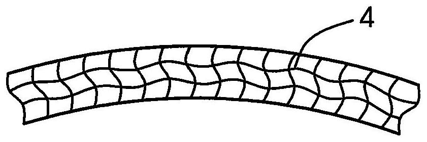
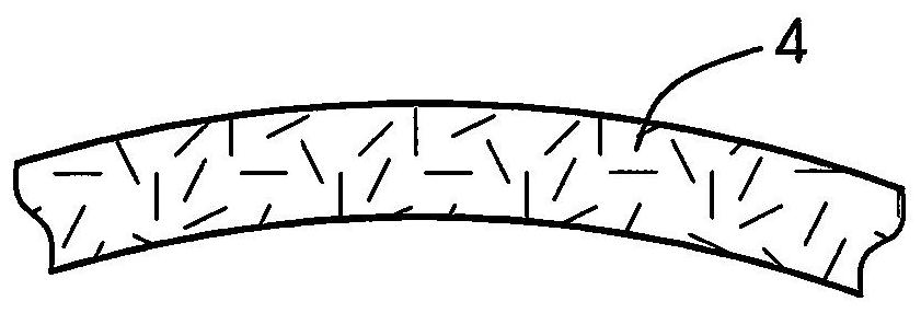
The invention relates to a die-cutting cylinder for die-cutting printing materials, which comprises a cylinder peripheral surface (2), a die-cutting plate (3) and a labyrinth or Porous or woven layer (4).

Description

Technical field [0001] The present invention relates to a die cutting roller for die-cutting material comprising a roller peripheral surface and a die cutting plate. Background technique [0002] Such die-cut rollers are used to rotate mold cutting paper and thick panels. [0003] A die-cutting roller is described, for example, in DE 101 47 486 A1, and the die cutting plate is magnetically held on the die cutting roller. The die-cut roller has an air opening for blowing air and / or suction air. The waste sheet is held on the die cutting roller by suction air and blown into the suction hood by spraying air. The remaining space is constructed into the die cutting plate, and the air opening takes over and blows through the remaining portion. The air opening is placed in the grille. [0004] Unfavorable, when manufacturing the die cutting board, the grid width limit of the grillers of the die-cutting waste is placed. Results The functional reliability and page sheets are very poor u...

Claims


Application Information

Patent Timeline
Patent Type & Authority Patents(China)
IPC IPC(8): B26D7/18B26D7/26B41G7/00
CPCB26D7/1854B26D7/1863B26D2007/2607B41G7/00B26F1/384B41F19/008B31B50/14
Inventor J·弗里德里希斯B·西茨曼W·柯尼希W·比特瑞驰A·维斯戈尔B·马斯
Owner HEIDELBERGER DRUCKMASCHINEN AG
Learn More