
Oil filtering device

A technology of oil filtering device and handle, which is applied in packaging, container handles, transportation and packaging, etc. It can solve the problems of time-consuming, reduce direct contact, improve work efficiency, and be easy to use

Inactive Publication Date: 2017-12-29
张家港保税区奇利国际贸易有限公司
View PDF3 Cites 0 Cited by
  • Summary
  • Abstract
  • Description
  • Claims
  • Application Information

AI Technical Summary

Problems solved by technology

But in this process, batch processing needs to be carried out one by one, which takes a lot of time, and at the same time, the staff need to be in direct contact with the anti-rust oil

Method used


Image

  • Oil filtering device

Examples


Embodiment Construction

[0016] The technical solutions in the embodiments of the present invention will be described in detail below in conjunction with the accompanying drawings in the embodiments of the present invention. Obviously, the described embodiments are only some of the embodiments of the present invention, not all of them. Based on the embodiments of the present invention, all other embodiments obtained by persons of ordinary skill in the art without making creative efforts belong to the protection scope of the present invention.

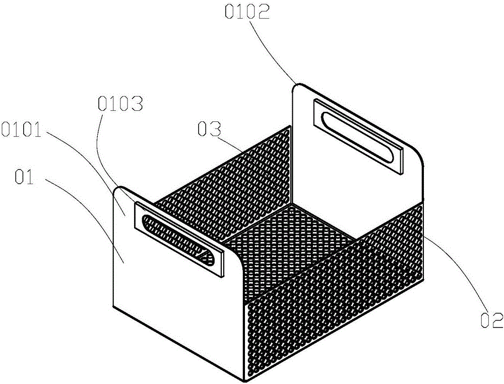
[0017] ginseng figure 1 As shown, the oil filter device in the embodiment of the present invention is a cuboid without a cover formed by bending a steel plate, and has a simple structure and is easy to use.

[0018] Preferably, all the bent seams of the oil filter device are welded to ensure the firmness of the whole device.

[0019] Preferably, the short end plates 01 on both sides of the oil filter device are provided with protruding handles 0101, and the tw...


PUM


Abstract

The invention discloses an oil filtering device. The oil filtering device is a cuboid bent through a steel plate, wherein the cuboid is not provided with a sealing cover. The novel oil filtering device is simple in structure and convenient to use; multiple workpieces can be soaked at a time, so that the work efficiency is improved; and direct contact between working personnel and rustproof oil is reduced.

Description

technical field [0001] The application relates to an oil filter device, which is used for immersing parts in antirust oil and filtering the oil for draining. Background technique [0002] Large quantities of metal products and spare parts, such as: bearings, measuring tools, cutting tools, hardware, standard parts, automobile and agricultural machinery parts and other small and medium-sized metal parts. Method: immerse clean metal parts in liquid In the anti-rust oil, when the oil is fully coated on the metal surface to a certain thickness of the oil film, take it out and drain it to complete the dip coating. But in this process, batch processing needs to be carried out one by one, which takes a lot of time, and at the same time, the staff need to be in direct contact with the anti-rust oil. Contents of the invention [0003] The object of the present invention is to provide an oil filtering device to overcome the deficiencies in the prior art. [0004] To achieve the ab...

Claims


Application Information

Patent Timeline
IPC IPC(8): B65D25/00B65D25/30
CPCB65D25/005B65D25/30
Inventor 赵胜
Owner 张家港保税区奇利国际贸易有限公司
Learn More