
Turbine vanes, turbines and aero engines

A technology of turbine guide vanes and turbine casings, which is applied in the direction of engine components, machines/engines, mechanical equipment, etc., which can solve the problems of difficult cooling of rotatable turbine guide vanes, achieve adjustability and improve work performance

Active Publication Date: 2019-07-26
AECC COMML AIRCRAFT ENGINE CO LTD
View PDF3 Cites 0 Cited by
  • Summary
  • Abstract
  • Description
  • Claims
  • Application Information

AI Technical Summary

Problems solved by technology

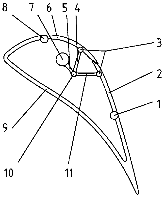
[0008] The purpose of the present invention is to propose a turbine guide vane, a turbine and an aero-engine to solve the problem of difficult cooling of the rotatable turbine guide vanes in the prior art

Method used


Image

  • Turbine vanes, turbines and aero engines
  • Turbine vanes, turbines and aero engines
  • Turbine vanes, turbines and aero engines

Examples


Embodiment Construction

[0030] The technical solutions in the embodiments of the present invention will be clearly and completely described below in conjunction with the drawings in the embodiments of the present invention. Apparently, the described embodiments are only some of the embodiments of the present invention, not all of them. Based on the embodiments of the present invention, all other embodiments obtained by persons of ordinary skill in the art without making creative efforts fall within the protection scope of the present invention.

[0031] In describing the present invention, it should be understood that the terms "center", "transverse", "longitudinal", "front", "rear", "left", "right", "upper", "lower", " The orientations or positional relationships indicated by "vertical", "horizontal", "top", "bottom", "inner" and "outer" are based on the orientations or positional relationships shown in the drawings, and are only for the convenience of describing the present invention and Simplifie...


PUM


Abstract

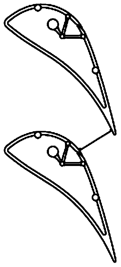
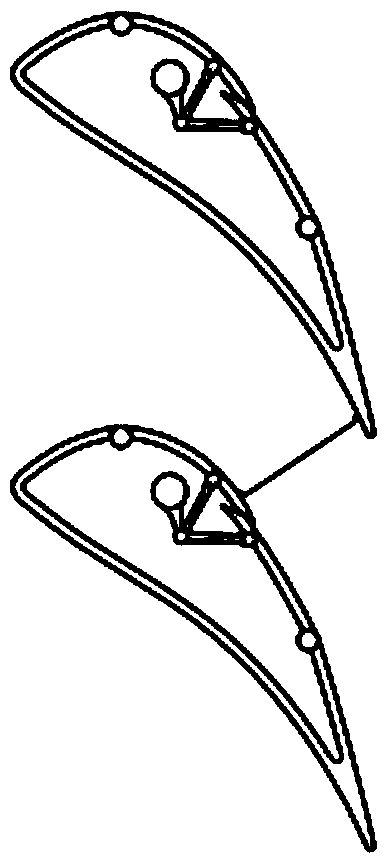
The invention relates to a turbine guide vane, a turbine and an aircraft engine. The turbine guide vane comprises a movable part and a fixed part (9), the fixed part (9) is fixed relative to a turbine case, the movable part is connected with the fixed part (9) and located on one side of the suction surface of the turbine guide vane, and the movable part can move relative to the fixed part (9) so as to change the flow area between every two adjacent turbine guide vanes. Compared with the manner that the front edge or the tail edge of the turbine guide vane is arranged to be of a rotatable structural form in the prior art, the turbine guide vane has the advantages that the movable part is arranged on one side of the suction surface of the turbine guide vane, cooling of the interior of the turbine guide vane is not influenced, the whole vane, from the front edge to the tail edge, of the turbine guide vane can be cooled by taking corresponding cooling measures, and the condition that the life is shortened due to the fact that some portions of the turbine guide vane are impacted by high-temperature fuel gas is prevented.

Description

technical field [0001] The invention relates to the technical field of turbines, in particular to a turbine guide vane, a turbine and an aeroengine. Background technique [0002] Turbine engine has a remarkable feature, that is, with the change of operating conditions, its performance changes more drastically, especially at different speeds or different inlet conditions (flight Mach number, etc.), its performance changes more diversely. The use of variable geometry turbine guide vanes can change the working relationship between the engine compression parts and turbine parts, so that both the compressor and the turbine work in a better state, or ensure that the compressor has sufficient stability margin; not only that, for dual Rotor turbine engine, by changing the flow area of ​​the guide vane of the low pressure turbine, can also change the speed difference of the high and low pressure rotors, realize the variable cycle function, improve the engine efficiency, and expand th...

Claims


Application Information

Patent Timeline
Patent Type & Authority Patents(China)
IPC IPC(8): F01D9/04
CPCF01D9/041
Inventor 严红明郑恒邓潇郑建弘谭智勇
Owner AECC COMML AIRCRAFT ENGINE CO LTD
Learn More