Production method of mortised and riveted impeller

A production method and technology of impellers, which are applied to parts of pumping devices for elastic fluids, non-variable pumps, machines/engines, etc., can solve the problems of low connection reliability between discs and blades, small fan structure, and production problems. Low efficiency and other problems, to achieve the effect of reducing energy consumption, stable impeller structure, and less production processes

Inactive Publication Date: 2017-12-29
常州恒益电机有限公司
View PDF4 Cites 3 Cited by
  • Summary
  • Abstract
  • Description
  • Claims
  • Application Information

AI Technical Summary

Problems solved by technology

[0002] The impeller is an important component of the fan. At present, the metal impeller of the existing fan generally adopts methods such as casting, machining and cutting. The above two methods are generally used to form an integrated structure and be used on larger fans or for The requirements are relatively high. For fans with small structures, such as the fans used on gas water heaters, the fan structure is small, and the impellers used are small and light. Body structure, the production method is to shape the wheel and blades separately, and then assemble the wheel and blades. The wheel and blades are generally connected by bonding or clipping. There is a slot, the end of the blade is a plug, and the size of the slot is larger than the plug. After the plug is inserted into the slot, it is necessary to pre-tighten the blade and the wheel. After the pre-tightening, press the part of the plug protruding from the slot to the On the outer end surface of the wheel disc, and then further compress the wheel disc and blades, there are many procedures and low production efficiency. The bonding method is used, the connection reliability between the wheel disc and the blades is low, and the service life is short

Method used


Image

  • Production method of mortised and riveted impeller
  • Production method of mortised and riveted impeller
  • Production method of mortised and riveted impeller

Examples


Embodiment 1

[0026] Embodiment 1: the production method of tenon riveting impeller, comprises the following steps:

[0027] Step 1, prepare materials:

[0028] Prepare the impeller lower plate, blade, impeller upper plate and shaft sleeve according to the design size requirements,

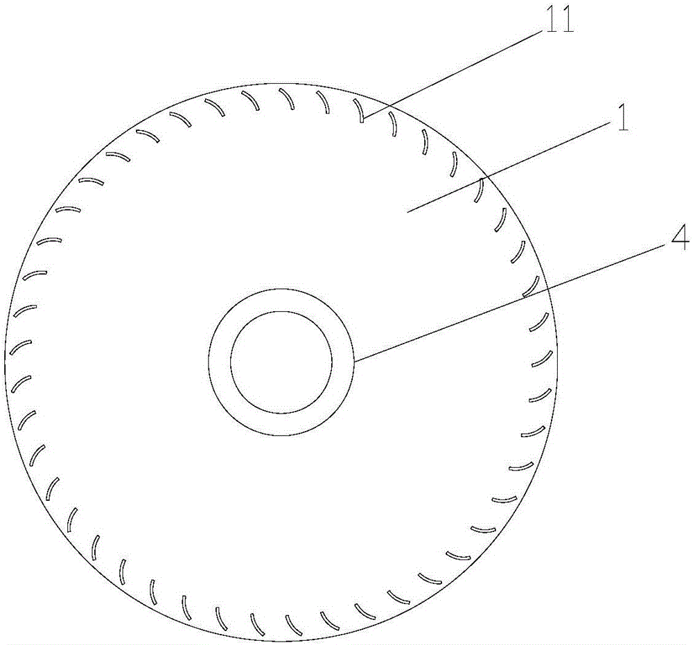
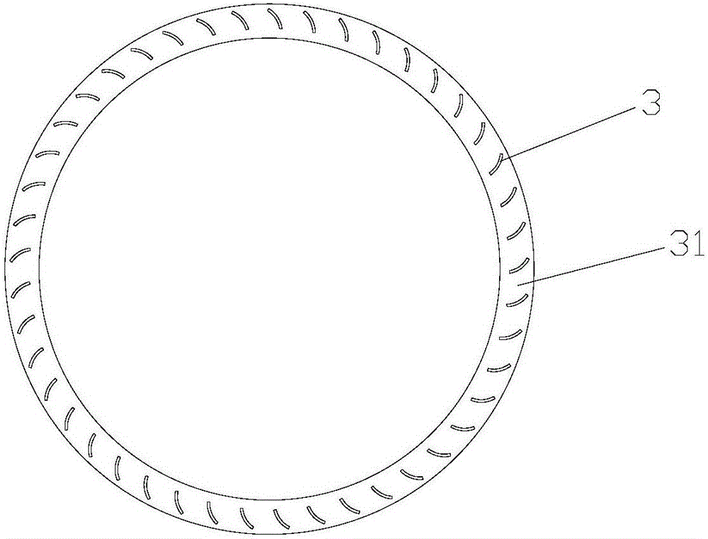
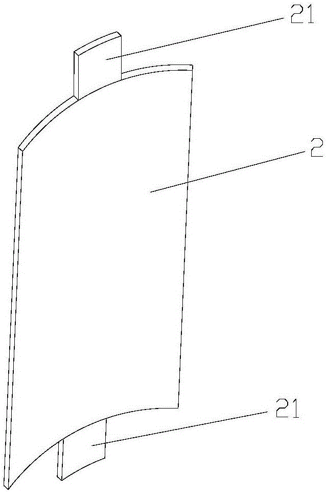
[0029] Among them, the outer surface of the impeller lower disk surface corresponds to the installation of the blades, and the lower disk mortises in a circular distribution are processed by stamping, and the outer surface of the impeller upper disk surface corresponds to the installation of the blades. The aluminum strip is shaped by the impact of the mold, and the two ends of the blade are respectively processed with tenons. The size and structure of the tenons are consistent with the size and structure of the upper plate mortises and the lower plate mortises;

[0030] Step two, assembly:

[0031] a. Assemble the shaft sleeve and the impeller bottom plate, place the impeller bottom plate horizontally on the...

Embodiment 2

[0039] The production method of the tenon riveting impeller comprises the following steps:

[0040] Step 1, prepare materials:

[0041] Prepare the impeller lower plate, blade, impeller upper plate and shaft sleeve according to the design size requirements,

[0042] Among them, the outer surface of the impeller lower disk surface corresponds to the installation of the blades, and the lower disk mortises in a circular distribution are processed by stamping, and the outer surface of the impeller upper disk surface corresponds to the installation of the blades. The aluminum strip is shaped by the impact of the mold, and the two ends of the blade are respectively processed with tenons. The size and structure of the tenons are consistent with the size and structure of the upper plate mortises and the lower plate mortises;

[0043] Step 2, assembling the impeller upper plate, blades and impeller lower plate;

[0044] a. Place the lower plate of the impeller horizontally on the ins...

Embodiment 3

[0052] The production method of the tenon riveting impeller comprises the following steps:

[0053] Step 1, prepare materials:

[0054] Prepare the impeller lower plate, blade, impeller upper plate and shaft sleeve according to the design size requirements,

[0055] Among them, the outer surface of the impeller lower disk surface corresponds to the installation of the blades, and the lower disk mortises in a circular distribution are processed by stamping, and the outer surface of the impeller upper disk surface corresponds to the installation of the blades. The aluminum strip is shaped by the impact of the mold, and the two ends of the blade are respectively processed with tenons. The size and structure of the tenons are consistent with the size and structure of the upper plate mortises and the lower plate mortises;

[0056] Step two, assembly:

[0057] a. Assemble the shaft sleeve and the impeller bottom plate, place the impeller bottom plate horizontally on the pre-instal...


PUM


Abstract

The invention belongs to the technical field of a motor impeller, in particular to a production method of a mortised and riveted impeller. The production method comprises the steps: step 1, material preparation: preparing a lower impeller tray, blades and an upper impeller tray as required, cutting lower tray mortises in the lower impeller tray, cutting upper tray mortises in the upper impeller tray, and processing tenons on the two ends of each blade; step 2, assembly: mounting a plurality of blades on the lower impeller tray and the upper impeller tray one by one, inserting the blade tenons on one side of the lower impeller tray into the lower tray mortises or tongue-and-grooves in the corresponding positions of the lower impeller tray, inserting the blade tenons on one side of the upper impeller tray into the upper tray mortises or tongue-and-grooves in the corresponding positions of the upper impeller tray, and thus obtaining an impeller packaging body; step 3, rivet-pressing: rivet-pressing the blade tenons of the impeller packaging body obtained in the step 2 and the insertion positions of the upper tray mortises or tongue-and-grooves and the lower tray mortises or tongue-and-grooves by using rivet-pressing equipment, riveting the blade tenons with the upper tray mortises or tongue-and-grooves and the lower tray mortises or tongue-and-grooves, and thus obtaining an impeller assembly. The production method has the advantages of less procedure, high production efficiency and stable impeller structure.

Description

technical field [0001] The invention belongs to the technical field of motor impellers, and in particular relates to a production method of tenon riveting impellers. Background technique [0002] The impeller is an important component of the fan. At present, the metal impeller of the existing fan generally adopts methods such as casting, machining and cutting. The above two methods are generally used to form an integrated structure and be used on larger fans or for The requirements are relatively high. For fans with small structures, such as the fans used on gas water heaters, the fan structure is small, and the impellers used are small and light. Body structure, the production method is to shape the wheel and blades separately, and then assemble the wheel and blades. The wheel and blades are generally connected by bonding or clipping. There is a slot, the end of the blade is a plug, and the size of the slot is larger than the plug. After the plug is inserted into the slot,...

Claims


Application Information

Patent Timeline
Patent Type & Authority Applications(China)
IPC IPC(8): F04D29/28F04D29/62
CPCF04D29/282F04D29/624
Inventor 邵江华何建平
Owner 常州恒益电机有限公司
Why Eureka
Try Eureka