
Determination method and system for demanded quantity of boiler fuel and adjustment method and system for boiler fuel

A boiler fuel and determination method technology, applied in the field of feedback regulation, can solve problems such as long interval time, inability to accurately correct the amount of fuel fed into the furnace in real time, and lagging analysis results, so as to avoid under-adjustment or over-adjustment and speed up the correction response speed , to avoid the effect of lengthy process

Active Publication Date: 2017-12-29
HANGZHOU HOLLYSYS AUTOMATION
View PDF5 Cites 2 Cited by
  • Summary
  • Abstract
  • Description
  • Claims
  • Application Information

AI Technical Summary

Problems solved by technology

The calorific value of fuel entered manually comes from chemical analysis, but the analysis cycle of chemical analysis is eight hours or one day, the interval is long, and the analysis results are lagging
Therefore, this method also cannot accurately correct the amount of fuel in the furnace in real time.

Method used


Image

  • Determination method and system for demanded quantity of boiler fuel and adjustment method and system for boiler fuel
  • Determination method and system for demanded quantity of boiler fuel and adjustment method and system for boiler fuel
  • Determination method and system for demanded quantity of boiler fuel and adjustment method and system for boiler fuel

Examples


Embodiment Construction

[0053] The following will clearly and completely describe the technical solutions in the embodiments of the present invention with reference to the accompanying drawings in the embodiments of the present invention. Obviously, the described embodiments are only some of the embodiments of the present invention, not all of them. Based on the embodiments of the present invention, all other embodiments obtained by persons of ordinary skill in the art without making creative efforts belong to the protection scope of the present invention.

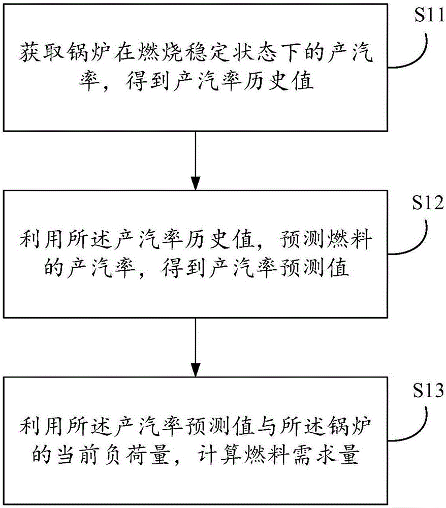
[0054] The embodiment of the present invention discloses a method for determining boiler fuel demand, see figure 1 as shown, figure 1 It is a flow chart of a method for determining boiler fuel demand disclosed in an embodiment of the present invention, including the following steps:

[0055] Step S11: Obtain the steam production rate of the boiler in a stable combustion state, and obtain the historical value of the steam production rate.

[005...


PUM


Abstract

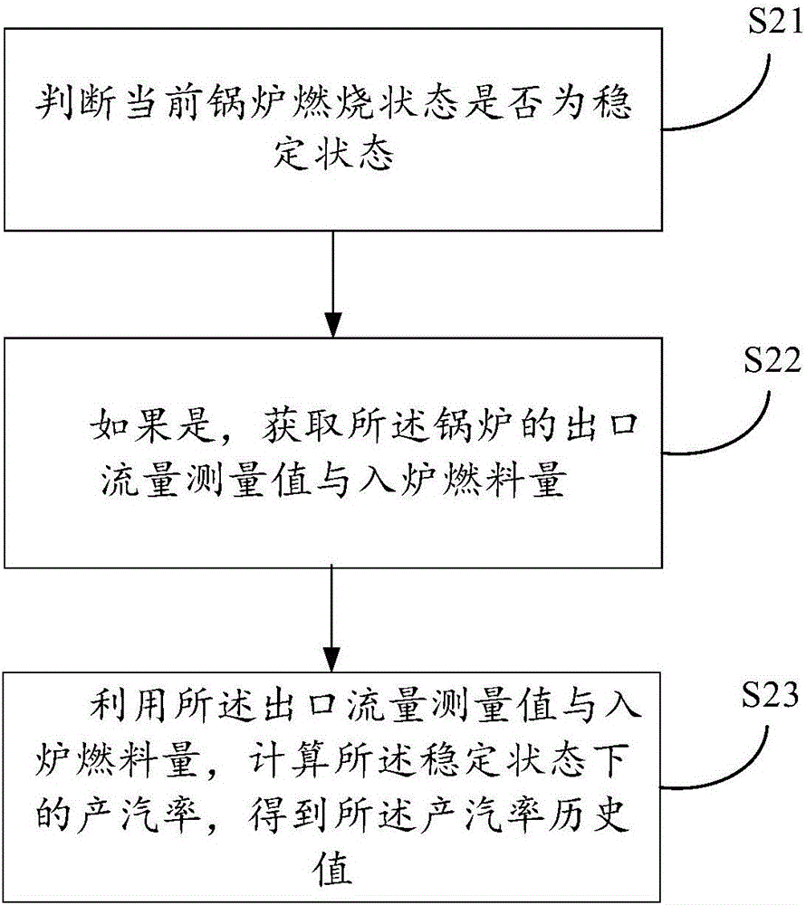
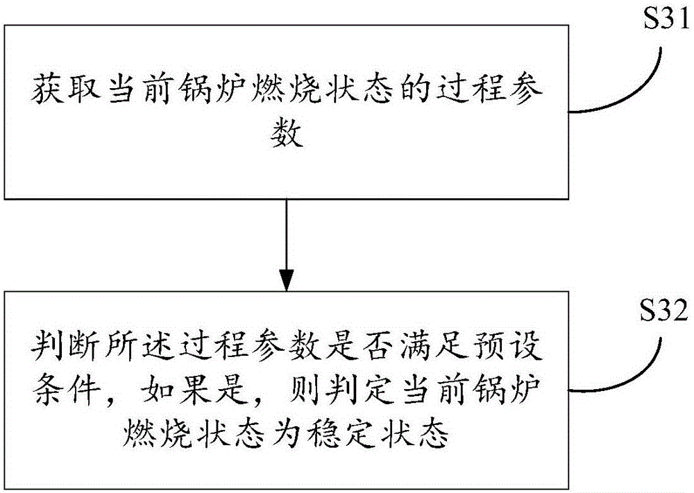
The invention discloses a determination method and system for the demanded quantity of boiler fuel and an adjustment method and system for the boiler fuel. The determination method comprises the following steps that the steam generating rate of a boiler in a combustion stabilization state is obtained so as to obtain a historical value of the steam generating rate; the steam generating rate of the fuel is predicted by utilizing the historical value of the steam generating rate so as to obtain the predicted value of the steam generating rate; and the demanded quantity of the fuel is calculated by utilizing the predicted value of the steam generating rate and the current load capacity of the boiler. According to the determination method and system for the demanded quantity of the boiler fuel and the adjustment method and system for the boiler fuel, in the combustion process of the boiler, when the fuel value changes due to various factors, the change can be embodied by the change of the steam generating rate, and therefore the demanded quantity of the fuel which is finally calculated through the historical value, obtained in a rolling mode, of the steam generating rate is accurate; and in addition, the situation that the fuel value changes greatly can be adapted to according to the adjustment range determined by the demanded quantity of the fuel and the adjustment limit amplitude of the fuel, the problem of under-adjustment or over-adjustment can be avoided, meanwhile, a tedious process of obtaining the fuel value by chemical analysis can also be avoided, and the correction response speed can be increased.

Description

technical field [0001] The invention relates to the field of feedback adjustment, in particular to a method for determining boiler fuel demand, an adjustment method and a system. Background technique [0002] During the combustion process of the boiler, due to various factors, the calorific value of the boiler fuel will change. When the calorific value of the fuel changes, in order to keep the utilization rate of the fuel within a reasonable range, it is necessary to adjust the amount of fuel newly introduced into the furnace. [0003] In the prior art, there are two ways to correct the fuel quantity. One is to approximate the calorific value of the fuel to a fixed value and adjust it through a feedback control loop (PID). The parameters of the amount of fuel entering the furnace are determined by the value of the combustion output, that is, the evaporation amount at the boiler outlet. But when the calorific value of the fuel changes, the preset fixed calorific value is n...

Claims


Application Information

Patent Timeline
IPC IPC(8): F22B35/00F23N1/00G06Q10/04G01D21/02
CPCF22B35/00F23N1/002F23N2223/10F23N2223/54F23N2241/10G01D21/02G06Q10/04
Inventor 李福军刘德成
Owner HANGZHOU HOLLYSYS AUTOMATION
Learn More