

Magnetic resonance scanning method, device and system
A technology of magnetic resonance scanning and scanning direction, which is applied in image data processing, medical science, image enhancement, etc. It can solve the problems of large differences in scanning accuracy and achieve the effect of improving uniformity, accuracy and accuracy
- Summary
- Abstract
- Description
- Claims
- Application Information
AI Technical Summary
Problems solved by technology
Method used
Image

Examples
Embodiment 1
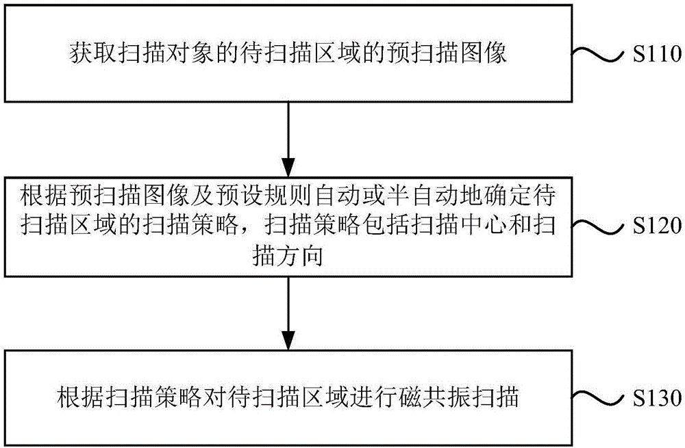
[0062] figure 1 It is a flow chart of a magnetic resonance scanning method provided in Embodiment 1 of the present invention. This embodiment is applicable to the situation of automatically determining the scanning strategy of the shoulder joint. This method can be implemented by a magnetic resonance scanning device provided in the embodiment of the present invention. For execution, the device may be implemented in software and / or hardware. see figure 1 , the method specifically includes:
[0063] S110. Acquire a pre-scanned image of a region to be scanned of the scanned object.
[0064] In this embodiment, a pre-scan is performed on the to-be-scanned area of the scanning object, and a pre-scanned image of the to-be-scanned area is obtained. Wherein, the pre-scanning refers to scanning the scanning object through a preset radio frequency sequence, and the preset radio frequency sequence is a radio frequency sequence for fast positioning and imaging of the scanning object,...
Embodiment 2
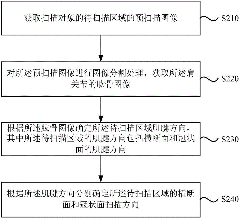
[0086] Figure 2A It is a flowchart of a magnetic resonance scanning method provided in Embodiment 2 of the present invention. On the basis of the above embodiments, a method for determining a scanning direction according to a pre-scan image is further provided. Accordingly, the method includes:
[0087] S210. Acquire a pre-scanned image of a region to be scanned of the scanned object.
[0088] S220. Perform image segmentation processing on the pre-scan image to acquire a humerus image of the shoulder joint.
[0089] S230. Determine the direction of the tendon in the region to be scanned according to the humerus image, wherein the direction of the tendon in the region to be scanned includes the direction of the tendon in the cross section and the coronal plane.
[0090] Wherein, the humerus image is pre-processed to determine the structural direction of each pixel in the humerus image, and the tendon direction is determined according to the structural direction of each pixel...
Embodiment 3
[0115] image 3 It is a magnetic resonance scanning method provided in the third embodiment of the present invention. On the basis of the above embodiments, a method for determining the scanning center according to the pre-scanning image is further provided. Accordingly, the method specifically includes:
[0116] S310. Acquire a pre-scanned image of an area to be scanned of the scanned object.
[0117] S320. Automatically or semi-automatically determine the scanning direction of the area to be scanned according to the pre-scanned image.
[0118] S330. Rotate the humerus image according to the scanning direction.
[0119] In this embodiment, when the scanning centers of different virtual planes are determined, the humerus image is rotated according to the scanning direction of the corresponding virtual plane. Exemplarily, if the scanning center of the cross section is determined, the humerus image is rotated according to the zero degree direction, the tendon direction of the...
PUM
 Abstract
Description
Claims
Application Information