Steel strip surface roll coating machine

A technology of roller coater and steel strip, which is applied in the field of roller coater frame and steel strip surface roller coating equipment, which can solve the problem of motor blockage of coating roller, precise reduction of film thickness, inability to adjust and control the pressure between rollers on one side, etc. problems, to achieve the effect of improving uniformity and accuracy, direct detection by roller pressure, and eliminating film thickness defects

Active Publication Date: 2019-10-11
SHANGHAI MEISHAN IRON & STEEL CO LTD
View PDF6 Cites 3 Cited by
  • Summary
  • Abstract
  • Description
  • Claims
  • Application Information

AI Technical Summary

Problems solved by technology

[0005] At present, the existing roller coating machine has the following problems in the roller coating process: 1) When the thickness of the two sides of the strip is inconsistent or the surface of the coating roller is worn on one side, the pressure between the two sides and the strip, the coating roller When the pressure on both sides of the liquid-taking roller is not consistent, due to the characteristics of the linear guide rail, the existing roller coating machine cannot effectively adjust and control the pressure between the rollers on one side, making it difficult to control the uniformity and stability of the coating thickness , the film thickness is accurately reduced; 2) The pressure sensor is set between the roller bearing seat and the driving device, and feedbacks the pressure on the roller surface when it is close

Method used


Image

  • Steel strip surface roll coating machine
  • Steel strip surface roll coating machine
  • Steel strip surface roll coating machine

Examples


Embodiment

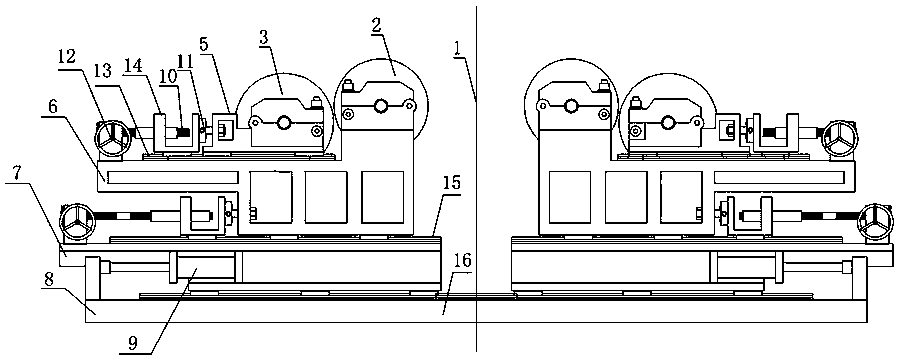
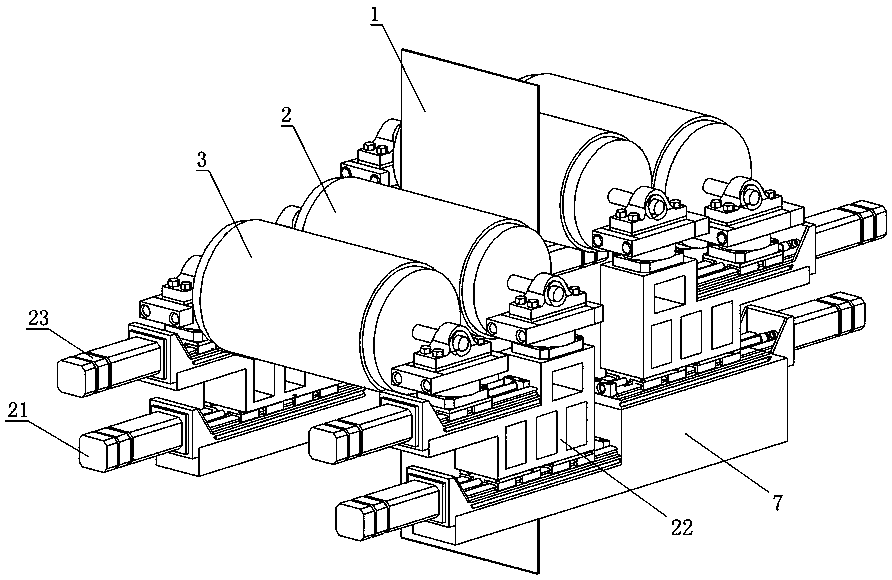
[0037] The placement of rolling mill transmission motors and other equipment in the steel rolling production line needs to be uniformly designed. The side close to the operation table is called the operation side, and the side where the transmission device is located is called the transmission side. Both ends of the coating roller 2 and the liquid-taking roller 3 are respectively supported on the bearing housing 25 through bearings, and the extension shafts of the coating roller 2 and the liquid-taking roller 3 at the transmission side are connected with the driving motor. The extension shafts of the coating roller 2 and the liquid-taking roller 3 located at the drive side are respectively connected with the drive motor through telescopic ball cages.

[0038] Such as Figure 5 As shown, the bearings on the coating roller 2 and the liquid-taking roller 3 at the drive side are all self-aligning floating bearings 26, and the bearings on the coating roller 2 and the liquid-takin...


PUM


Abstract

The invention relates to a steel strip surface roll coating machine, and belongs to the technical field of cold roll coating equipment. The steel strip surface roll coating machine comprises a coatingroller, a liquid take-up roller and a driving motor, the two ends of each of the coating roller and the liquid take-up roller are supported on bearing seats through bearings, and extending-out shafts, located at the transmission side, of the coating roller and the liquid take-up roller are connected with the driving motor. The steel strip surface roll coating machine is characterized in that thebearings located at the transmission side and on the coating roller and the liquid take-up roller are center-adjusting floating bearings, the bearings located on the operation side and on the coatingroller and the liquid take-up roller are self-center-adjusting roller bearings, and the bearing seats are fixed on a rotatable rotating platform. The steel strip surface roll coating machine can realize free adjustment of the single-side pressure between the coating roller and strip steel and between the liquid take-up roller and the coating roller, film thickness defects caused by abrasion of theroller face of the coating roller and the coincident thicknesses of the two sides of the strip steel can be effectively eliminated, the uniformity and precision of the film thickness are improved, and the stable quality of a coating film on the surface of the steel strip is ensured.

Description

technical field [0001] The invention relates to a roll coating equipment for the surface of a steel strip, in particular to a roll coating machine frame, which belongs to the technical field of cold rolling roll coating equipment. Background technique [0002] In order to meet the corrosion resistance requirements of home appliances and industrial equipment on the surface of steel plates, it also provides good surface coating properties, heat and humidity resistance, and fingerprint resistance for home appliances and automotive sheet products, and prevents white rust during transportation and processing. Defects, in the product post-processing process of the cold-rolled hot-dip galvanized production line, the roll coater is commonly used to apply the specified chemical coating to the surface of the strip. [0003] Existing roller coating processes such as figure 1 As shown, the roller coater is usually installed vertically and symmetrically with four rollers, and is mainly ...

Claims


Application Information

Patent Timeline
IPC IPC(8): B05C1/08B05C11/10
CPCB05C1/0834B05C1/0865B05C11/10
Inventor 陈绍林刘金华
Owner SHANGHAI MEISHAN IRON & STEEL CO LTD
Why Eureka
Try Eureka