Automatic tuning device for transmitter loop antenna and tuning method based on the device

An automatic tuning and loop antenna technology, applied in the field of antenna tuning, can solve unwise problems

Active Publication Date: 2019-07-23
WUXI ZETAI MICROELECTRONICS
View PDF5 Cites 0 Cited by
  • Summary
  • Abstract
  • Description
  • Claims
  • Application Information

AI Technical Summary

Problems solved by technology

However, in a single-transmission radio frequency chip, it is obviously unwise to design a receiving link for automatic antenna tuning.

Method used


Image

  • Automatic tuning device for transmitter loop antenna and tuning method based on the device
  • Automatic tuning device for transmitter loop antenna and tuning method based on the device
  • Automatic tuning device for transmitter loop antenna and tuning method based on the device

Examples


Embodiment 1

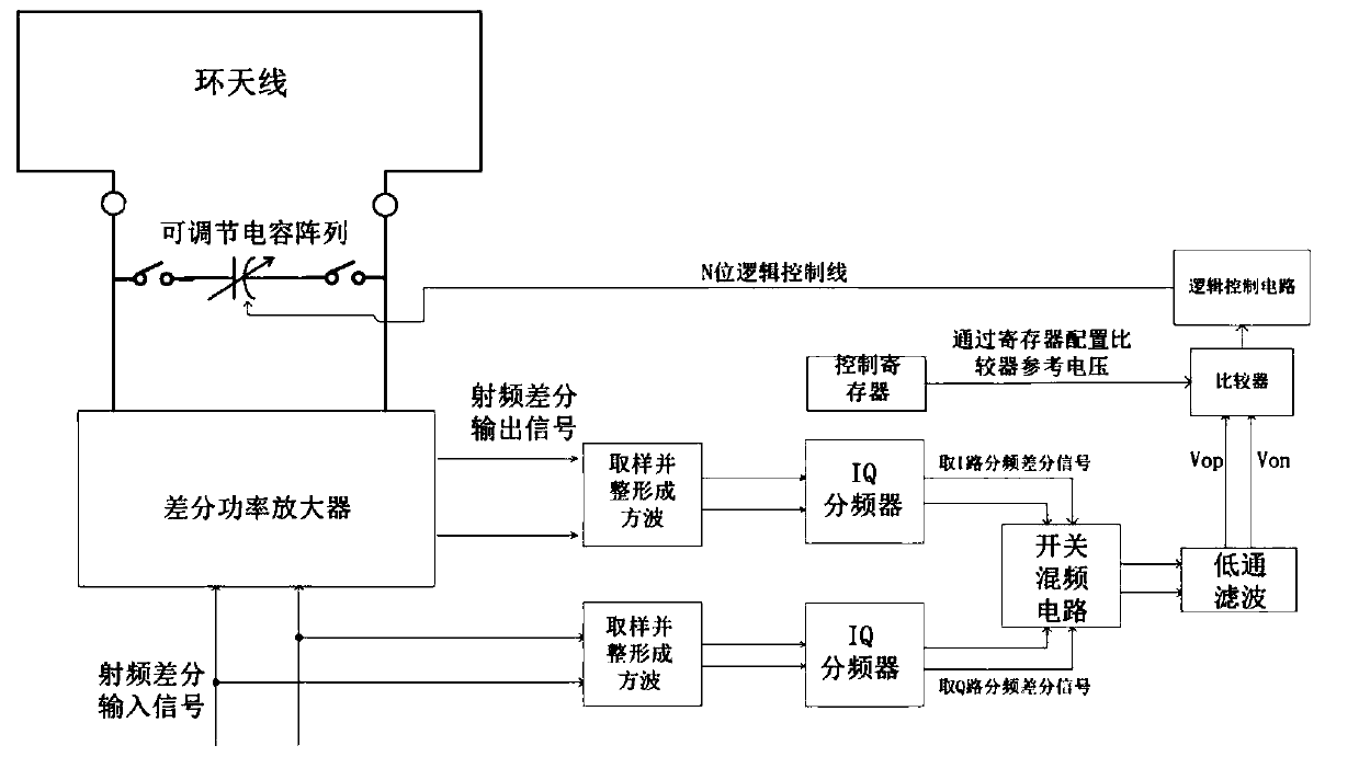
[0049] Such as figure 1 As shown, in order to realize the automatic tuning technology of transmitter loop antenna, the present invention provides a kind of automatic tuning device of transmitter loop antenna, including adjustable capacitor array, differential power amplifier and tuning control device;

[0050] The differential power amplifier is connected to the loop antenna, and is used to amplify the differential radio frequency input signal and then radiate outward through the loop antenna;

[0051]The tuning control device is respectively connected to the differential power amplifier and the adjustable capacitor array, judges whether the loop antenna is detuned according to the phase difference between the differential radio frequency input signal and the differential radio frequency output signal of the differential power amplifier, and outputs digital control instructions to the adjustable capacitor array;

[0052] The adjustable capacitor array and the loop antenna are...

Embodiment 2

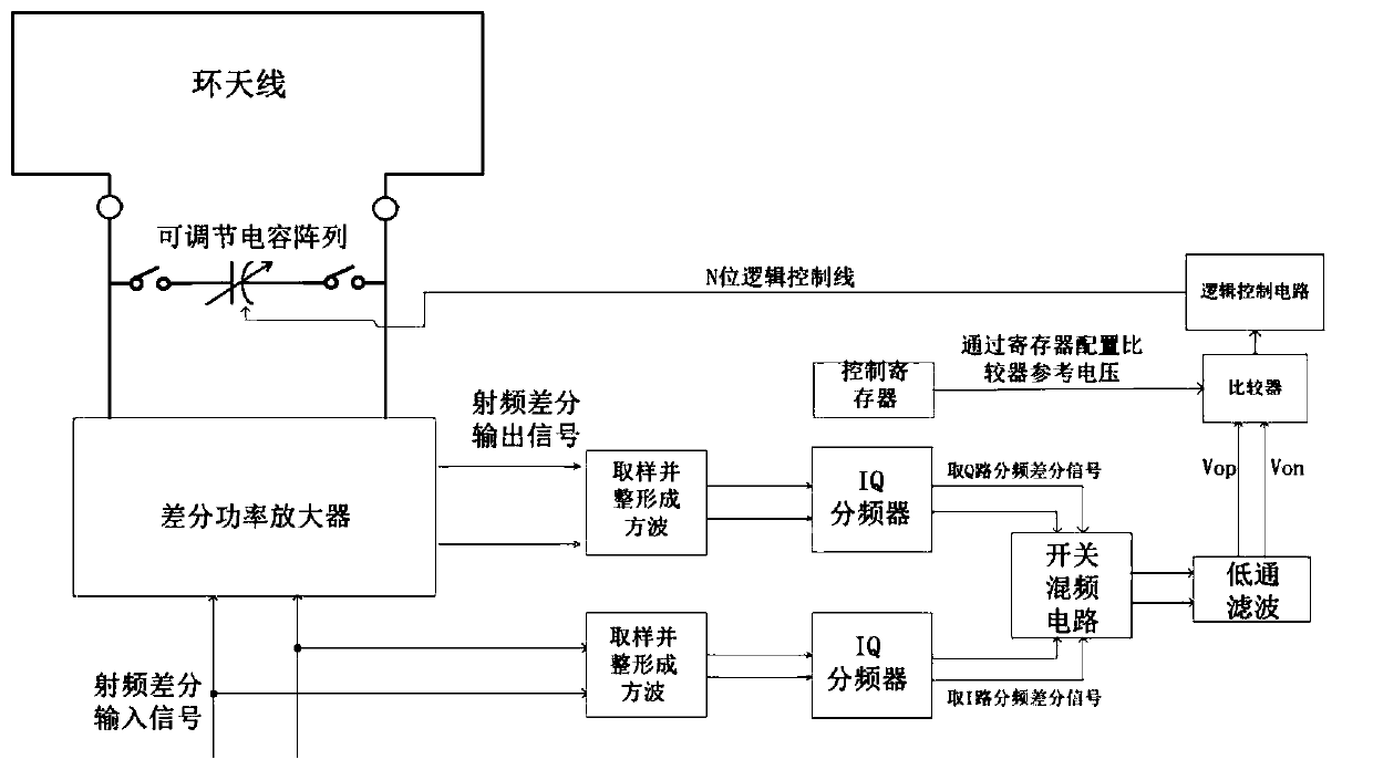
[0087] The difference between this embodiment and Embodiment 1 is that: figure 2 As shown, in step 5, the Q-channel frequency-divided differential signal of the differential radio frequency output signal and the I-channel frequency-divided differential signal of the differential radio frequency input signal are extracted for mixing processing to obtain a mixed output differential signal.

[0088] At this time, if the mixed frequency differential DC voltage is less than the preset reference DC voltage, that is, the phase difference between the I-channel frequency-divided differential signal of the differential RF output signal and the Q-channel frequency-divided differential signal of the differential RF input signal is 90 degrees, then the The output results of the lead comparator and the lag comparator are both "0";

[0089] If the mixing differential DC voltage is negative and greater than the preset reference DC voltage, that is, the phase difference between the I-way freq...


PUM


Abstract

The invention provides an automatic tuning device of a transmitter loop antenna and a tuning method based on the device. The automatic tuning device comprises an adjustable capacitor array, a differential power amplifier and a tuning control device; the tuning method based on the device comprises the following steps: presetting a reference voltage; synchronously processing a differential radio frequency input signal and a differential radio frequency output signal; configuring the capacitance value of the adjustable capacitor array as a median; sampling the differential radio frequency input signal and the differential radio frequency output signal, performing IQ orthogonal frequency division and performing mixing, filtering a high frequency component in a mixing output differential signal to obtain a mixing output DC voltage, and performing look-ahead comparison and lagging comparison of the phase between the differential radio frequency input signal and the differential radio frequency output signal according to the mixing output DC voltage and the reference voltage, judging whether the loop antenna is in a resonance state, outputting a digital control instruction to the adjustable capacitance array, and adjusting the capacitance size of the adjustable capacitance array.

Description

technical field [0001] The invention relates to the field of antenna tuning, in particular to an automatic tuning device for a transmitter loop antenna and a tuning method based on the device. Background technique [0002] An antenna is a device that radiates into space or receives electromagnetic waves from space in a radio transceiver system. Among them, the loop antenna is the most widely used antenna for short-distance wireless communication, because the loop antenna only needs to wind a wire into a certain shape or wire it on a PCB board into a certain shape, such as a circle, a square, etc. However, there are some non-ideal factors in the loop antenna, such as the parasitic parameter effect and inconsistency on the circuit board, and the proximity of human hands or other metal objects to the loop antenna will cause the loop antenna to detune and reduce the transmission power. So an automatic tuning mechanism is needed to ensure the performance of the antenna. [0003...

Claims


Application Information

Patent Timeline
Patent Type & Authority Patents(China)
IPC IPC(8): H04B1/04
CPCH04B1/04H04B1/0475H04B2001/0408
Inventor 谢鹏
Owner WUXI ZETAI MICROELECTRONICS
Why Eureka
Try Eureka