
Method for coupling a laser beam into a liquid jet beam

A laser beam, liquid technology, applied in the direction of laser welding equipment, metal processing equipment, welding equipment, etc.

Active Publication Date: 2019-07-05
AVONISYS AG
View PDF6 Cites 0 Cited by
  • Summary
  • Abstract
  • Description
  • Claims
  • Application Information

AI Technical Summary

Problems solved by technology

However, in order to materialize a workpiece with a liquid jet-guided laser beam, the laser power must exceed the damage threshold of the workpiece material

Method used


Image

  • Method for coupling a laser beam into a liquid jet beam
  • Method for coupling a laser beam into a liquid jet beam
  • Method for coupling a laser beam into a liquid jet beam

Examples


Embodiment Construction

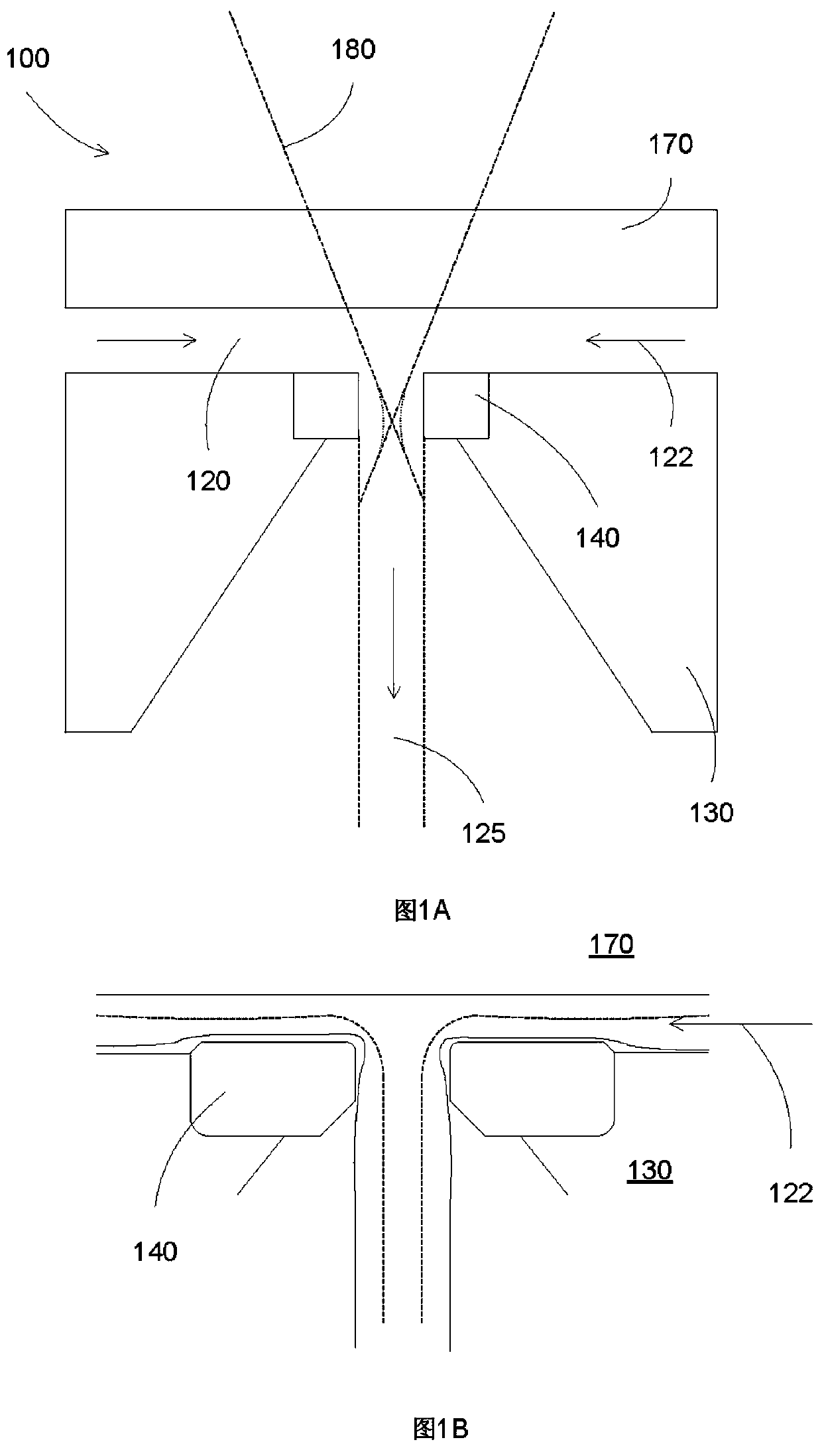
[0018] In some embodiments, the present invention relates to a liquid jet guided laser system that can generate a laser beam contained within a liquid jet. Laser technology is suitable for a wide variety of material processing tasks such as cutting, drilling, welding, marking, engraving and ablating materials. Almost all materials such as metals, metal alloys, ceramics, diamonds, synthetic diamonds, carbon fibers, sapphires, quartz, glass, plastics, etc. can be processed. In almost all cases, a focusing lens is used to focus the laser light into a very small spot, allowing the laser energy to exceed the damage threshold of the workpiece material to process the workpiece. The workpiece must therefore be precisely aligned at the laser focus point at all times during the entire process. In liquid jet-guided laser technology, a coupling unit is used to couple the laser focus into a thin liquid jet, so that the laser focus energy is kept over the entire length of the liquid jet. ...


PUM


Abstract

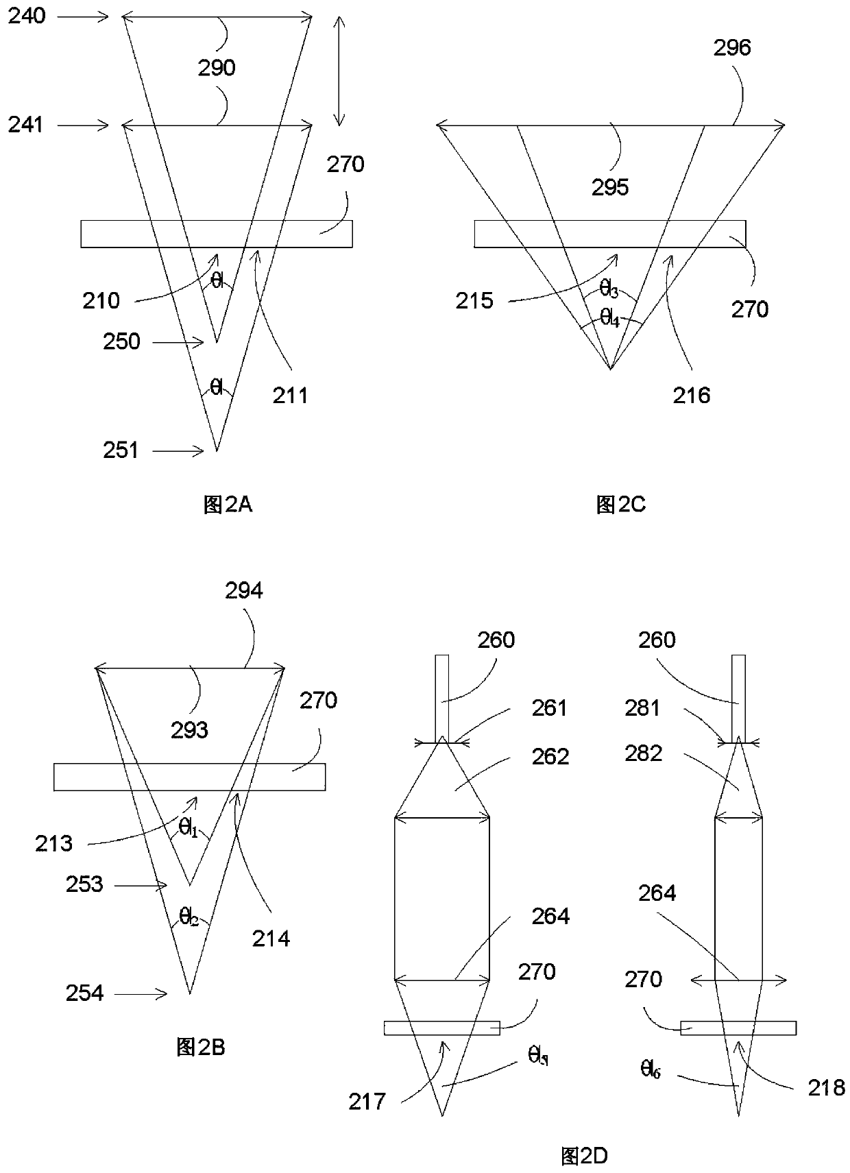
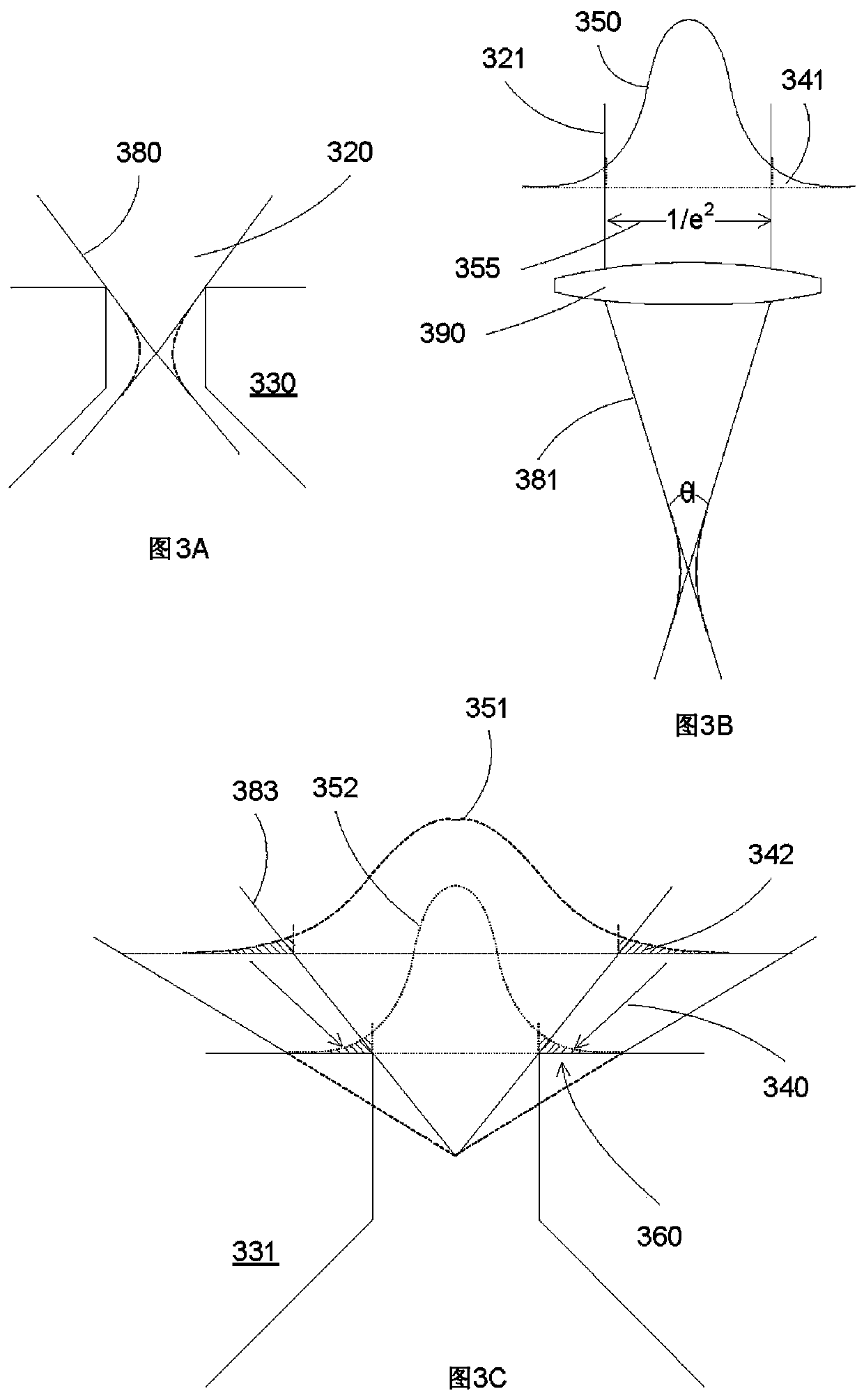
By setting the parameters of the liquid jet-guiding laser system according to the best relationship linking the laser focus, focus cone angle, laser beam energy distribution profile and nozzle geometry, high power can be achieved by utilizing the high lifetime performance of nozzles 130, 140 and protective window 170. The laser beam 180 is reliably coupled into the liquid jet 125 in the volume jet guiding laser system.

Description

Background technique [0001] Guiding light inside a liquid jet, light guiding of a laser having an energy level below the material damage threshold is well known and does not require precise alignment of the light into the liquid jet. However, in order to use a liquid jet to direct a laser beam for material treatment of a workpiece, the laser power must exceed the damage threshold of the workpiece material. In this case, the precise focus alignment of the laser beam to the liquid jet as well as the hydrodynamic effects of the liquid jet play a very important role and must therefore be precisely considered. [0002] In order to exploit this technology in an industrial environment where unmanned 3-shift operation is required, it is very important that the liquid jet laser process can be operated stably without interruption for long periods of time while providing high laser power for workpiece processing. Without proper focus alignment, the power level of many lasers is so high ...

Claims


Application Information

Patent Timeline
IPC IPC(8): B23K26/14
CPCB23K26/146B23K26/04B23K26/0648
Inventor 加布·延冈特海霸·吉荣
Owner AVONISYS AG
Learn More