

Attack detection device
An attack detection and detection part technology, applied in the field of attack detection devices, can solve the problem of inability to insert error frames, and achieve the effect of improving security and preventing camouflage attacks
- Summary
- Abstract
- Description
- Claims
- Application Information
AI Technical Summary
Problems solved by technology
Method used
Image

Examples
Embodiment approach 1
[0046]In this embodiment, first, the outline of CAN and the details of a short-circuit attack will be described, and then the configuration and operation of the attack detection device according to this embodiment will be described.
[0047]
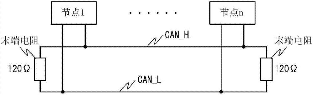
[0048] figure 2 It is a figure which shows the bus structure of CAN.
[0049] The CAN bus is a linear structure using two signal lines CAN_H and CAN_L, with 120Ω as the end at both ends. In addition, a plurality of nodes of node 1 to node n are respectively connected to the CAN bus line via CAN transceivers. These nodes are able to have equal access to the bus in a multi-master manner. In CAN, serial communication is carried out by using the differential voltage of CAN_H and CAN_L to transmit signals.
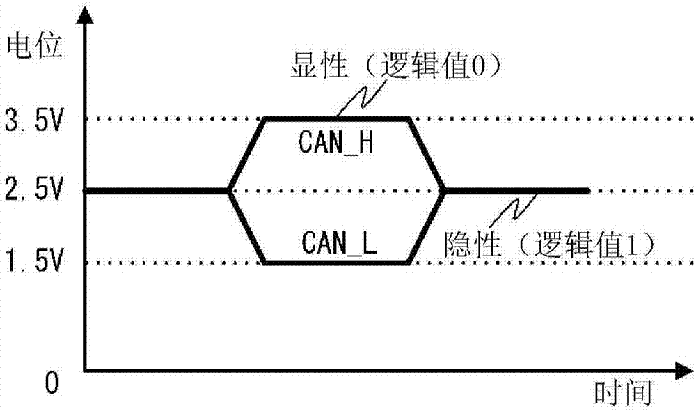
[0050] image 3 It is a diagram showing the signal level of high-speed CAN.
[0051] Such as image 3 As shown, the state in which the potential difference between CAN_H and CAN_L is large is called dominant, and a logical value ...
Embodiment approach 2
[0104] In Embodiment 1, a case where a short-circuit attack is detected by monitoring the potential difference between two CAN lines is described. Next, an embodiment in which a short-circuit attack is detected by monitoring the impedance between two CAN lines will be described.
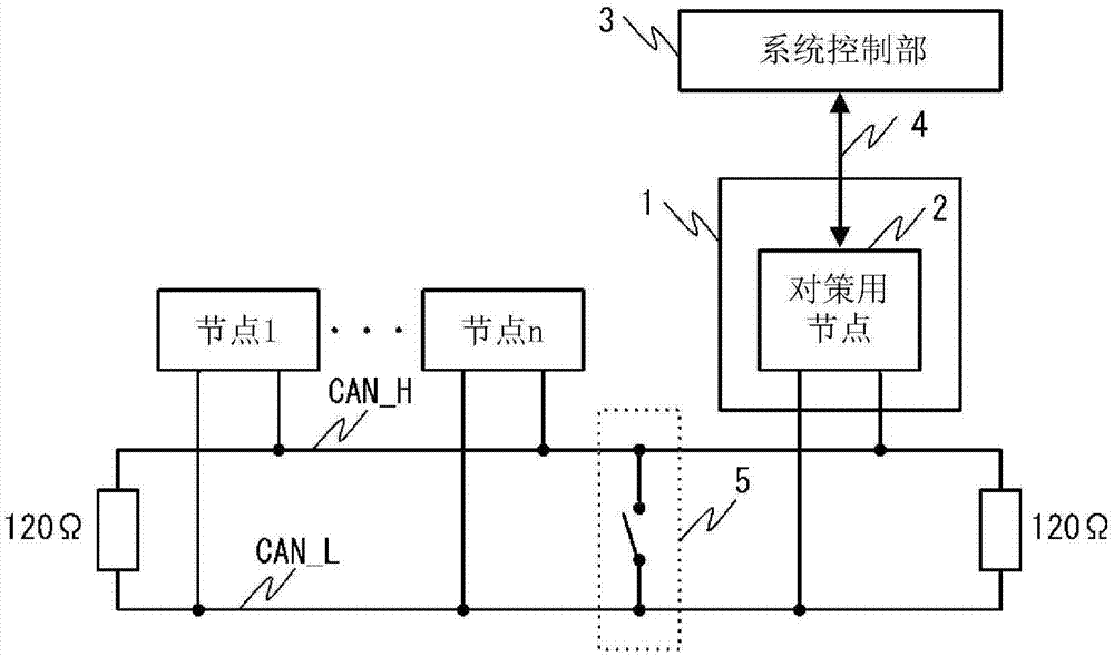
[0105] Figure 10 It is a figure which shows an example of the structure of the countermeasure node 2 which performs impedance monitoring.
[0106] exist Figure 10 in, instead of Figure 9 The AD converter 9 is provided with an impedance monitor 11 . other structures with Figure 9 same.
[0107] In this embodiment, the impedance between two CAN lines is measured by the impedance monitor 11 .
[0108] Figure 11 It is a diagram showing a configuration example of the impedance monitor 11 .
[0109] exist Figure 11 Among them, the impedance monitor 11 has a resistor 12 and an AD converter 13 . In addition, the impedance monitor 11 is not limited to any circuit or element as long as it can me...
Embodiment approach 3
[0113] In Embodiment 2, the case where a short-circuit attack is detected by monitoring the impedance between two CAN lines is described. Next, an embodiment in which a short-circuit attack is detected by monitoring the current between two CAN lines will be described.
[0114] Figure 12 It is a diagram showing a configuration example when current monitoring is performed.
[0115] In this embodiment, unlike the case of monitoring the potential difference or impedance, it is not implemented inside the countermeasure node 2, but is implemented on the power supply circuit of the system using CAN, or on the power line or power cable connecting the power supply circuit and CAN. . This is because even if the current flowing in a specific node connected to CAN is monitored, the entire current flowing between the two power supplies (3.5V and 1.5V) of CAN is not monitored.
[0116] exist Figure 12 Among them, a current monitor 14 is inserted in series between the power supply of CA...
PUM
 Abstract
Description
Claims
Application Information