Arrangement of an impeller on a rotating part and method for producing the arrangement

A technology of rotating parts and impellers, applied in the field of producing such components, can solve disadvantages, difficulties and other problems

Active Publication Date: 2018-01-02
ZIEHL ABEGG AG
View PDF10 Cites 1 Cited by
  • Summary
  • Abstract
  • Description
  • Claims
  • Application Information

AI Technical Summary

Problems solved by technology

[0012] However, the solution to the problem presented in the prior art is also disadvantageous, since when the impeller slides on it, the surface contact is present from the beginning, obtaining space only in the area of ​​the recess formed between them with a small radius
The press-fitting process still requires force and is difficult and there is a risk that, due to the dimensions of the sections of the ring-shaped blank that are intended to contact, the ring-shaped blank will The sections of the blank are supported on the rotor surface over the entire circumference, causing the same problems that existed before

Method used


Image

  • Arrangement of an impeller on a rotating part and method for producing the arrangement
  • Arrangement of an impeller on a rotating part and method for producing the arrangement
  • Arrangement of an impeller on a rotating part and method for producing the arrangement

Examples


Embodiment Construction

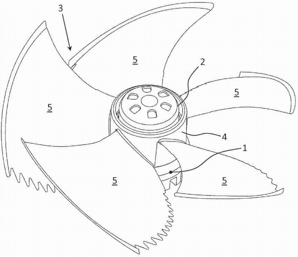
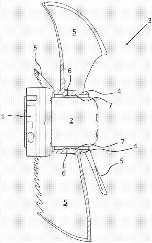
[0035] figure 1 An assembly according to the invention is shown schematically, comprising an electric motor 1 with a rotor 2 to which an impeller, hereinafter referred to as fan wheel 3 , is press-fitted. The non-rotational connection between the hub 4 of the fan wheel 3 and the rotor 2 or the surface of the rotor 2 is produced by a press fit.

[0036] The blades 5 are provided with aerodynamic features which do not play a role with regard to the teaching according to the invention.

[0037] At this point it should be noted that the fan wheel 3 is press-fitted onto the rotor 2 in order to form a specific flow direction. For the opposite flow direction, without changing the type and design of the fan wheel 3, it can be formed by press-fitting the fan wheel 3 on the rotor facing in the other direction.

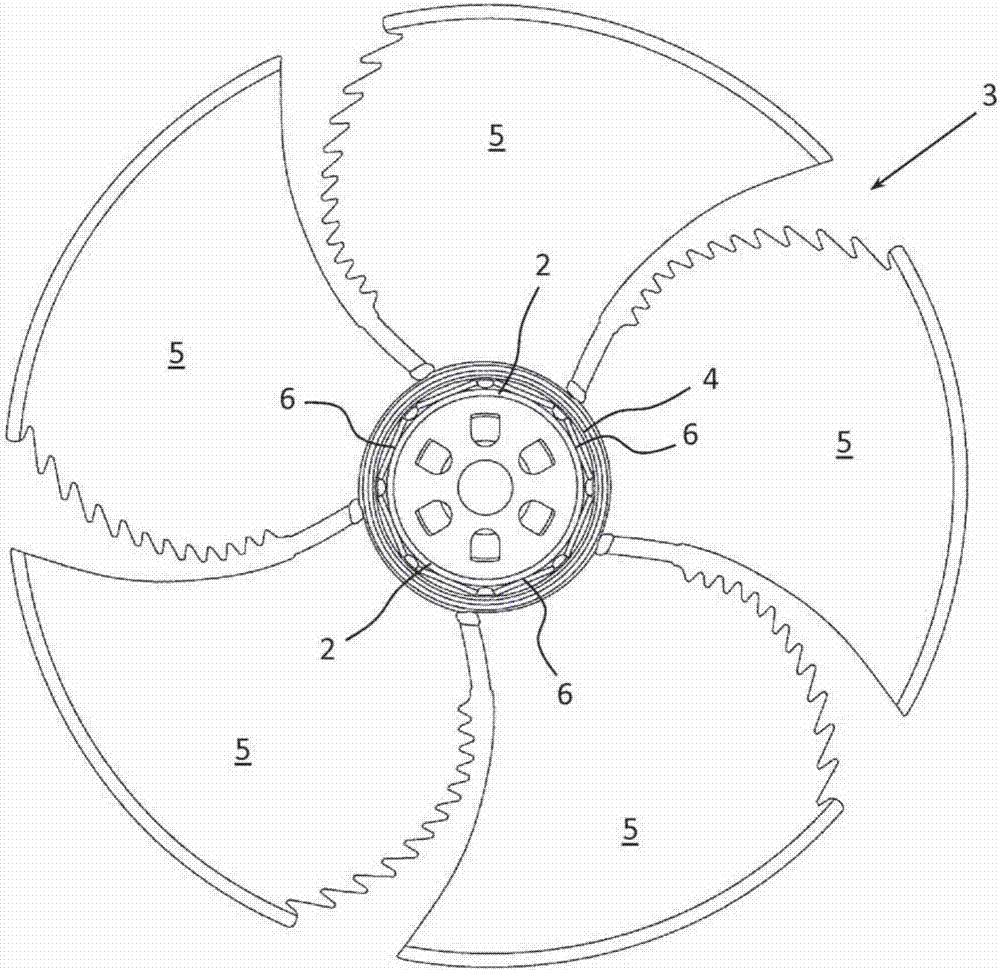
[0038] figure 2 shown in top view figure 1 , wherein it can be seen in the schematic diagram that the polygonal annular blank 6 is between the hub 4 of the fan wheel 3 and ...


PUM


Abstract

An arrangement of an impeller (3) on a rotating part, preferably on an electric motor (1), in particular on an external rotor motor, wherein the torque of the motor (1) is transmitted to the impeller(3) by a rotationally secure connection between the rotor (2) of the motor (1) and the impeller (3) or its impeller hub (4), and wherein the connection is created by means of a press fit between the impeller hub (4) and the rotor (2), with integration of a sleeve (6) which is preferably securely assigned to the impeller hub (4) and which takes up mechanical stresses, is characterized in that the sleeve (6) is polygonal and is pressed onto the surface of the rotor (2), with at least minor deformation, forming axial contact surfaces. Also specified is a method for producing such an arrangement.

Description

technical field [0001] The invention relates to an impeller assembly on a rotating member, preferably on an outer rotor motor. The rotating member may also be a shaft formed eg in an inner rotor motor or a hub or a disc eg in a belt drive. In any case, the term "rotary member" should be understood in the broadest sense. For simplicity, reference will be made below to the impeller assembly on an electric motor, in particular an outer rotor motor. [0002] For common assemblies, the motor's torque is transmitted to the impeller through a non-rotating connection between the motor's rotor and the impeller or its impeller hub. This connection is carried out by means of an interference fit (press fit) integrating an annular blank between the impeller hub and the rotor, which is permanently dedicated to the impeller hub, mechanically absorbing tension. With regard to being permanently dedicated, it should be noted that the impeller or impeller hub and the annular blank may be two ...

Claims


Application Information

Patent Timeline
IPC IPC(8): F04D25/06F04D29/26F04D29/64
CPCF04D25/0613F04D29/263F04D29/646
Inventor S·罗斯勒迈克尔·鲁德纳尔
Owner ZIEHL ABEGG AG
Why Eureka
Try Eureka