
Clamping type pipeline conveying device for municipal engineering construction

A technology for engineering construction and handling devices, which is applied in the direction of transportation and packaging, conveyor objects, etc., can solve the problems of high work intensity, large manual participation, poor usability, etc., to reduce labor intensity, increase safety, and novel design Effect

Inactive Publication Date: 2018-01-05
SHIYAN SIYUAN AGRI & FORESTRY TECH CO LTD
View PDF1 Cites 2 Cited by
  • Summary
  • Abstract
  • Description
  • Claims
  • Application Information

AI Technical Summary

Problems solved by technology

At present, the laying of pipelines is usually completed manually with the help of cranes. In the process, the degree of manual participation is large, and manual handling is usually used, which has a large workload and low efficiency.
Moreover, the length of drainage pipes is different according to their use and distribution position. For larger, longer and heavier pipes, it is extremely inconvenient to carry, and it is also very easy to cause damage and other accidents during the transportation process.
[0004] Chinese patent (notification number: CN205772841U) discloses a lift-type pipeline handling device, although the device increases the handling efficiency of the pipeline and reduces the work intensity to a certain extent, but in the actual use process, the lifting rod is still manually lifted , the working intensity is still high, and at the same time, the device’s grip on the pipeline is not very firm, which is prone to looseness and poor usability

Method used


Image

  • Clamping type pipeline conveying device for municipal engineering construction
  • Clamping type pipeline conveying device for municipal engineering construction
  • Clamping type pipeline conveying device for municipal engineering construction

Examples


Embodiment Construction

[0022] It should be noted that, in the case of no conflict, the embodiments of the present invention and the features in the embodiments can be combined with each other.

[0023] In describing the present invention, it should be understood that the terms "center", "longitudinal", "transverse", "upper", "lower", "front", "rear", "left", "right", " The orientations or positional relationships indicated by "vertical", "horizontal", "top", "bottom", "inner" and "outer" are based on the orientations or positional relationships shown in the drawings, and are only for the convenience of describing the present invention and Simplified descriptions, rather than indicating or implying that the device or element referred to must have a particular orientation, be constructed and operate in a particular orientation, and thus should not be construed as limiting the invention. In addition, the terms "first", "second", etc. are used for descriptive purposes only, and should not be understood ...


PUM


Abstract

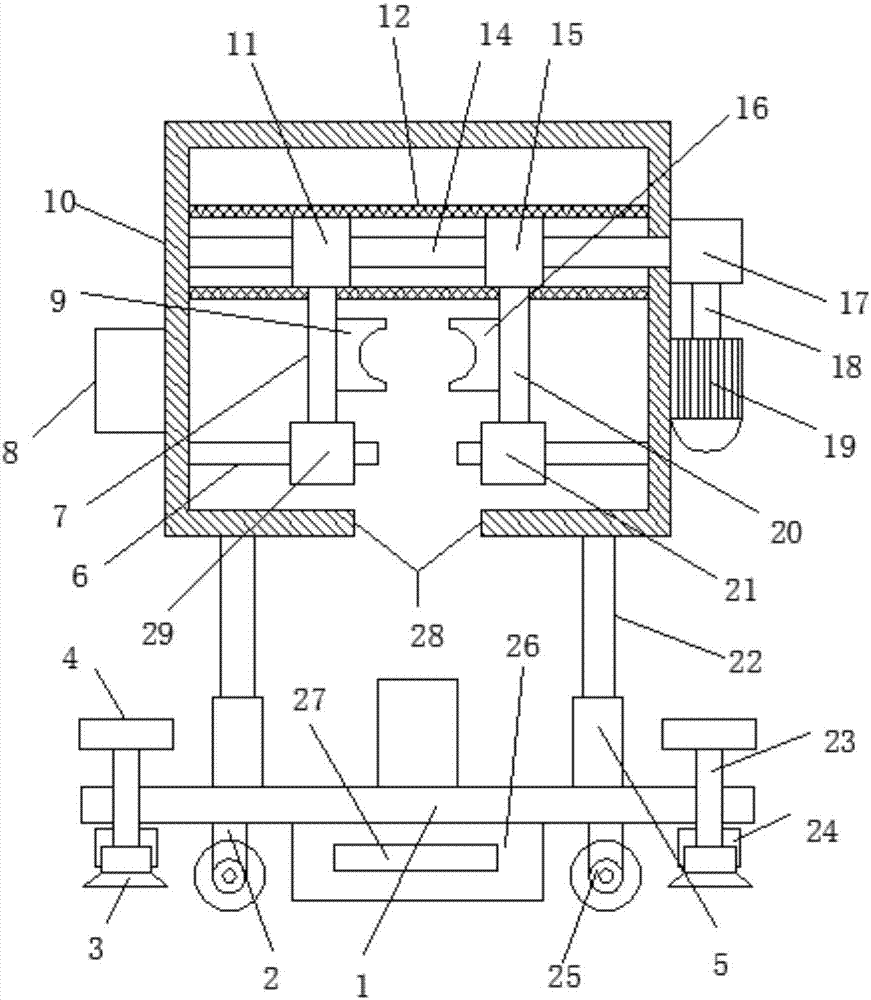
The invention discloses a clamping type pipeline conveying device for municipal engineering construction. The clamping type pipeline conveying device comprises a support seat. Traveling frames are connected to the two sides of the lower end of the support seat. Rotary columns are connected to the middles of the two ends of the support seat. Hydraulic cylinders are connected to the two sides of theupper end of the support seat. Hydraulic shafts are connected to the upper ends of the hydraulic cylinders. Conveying boxes are connected to the upper ends of the hydraulic shafts. Guide sleeves arearranged at the upper ends in the conveying boxes. Rotary screw rods are arranged in the middles in the guide sleeves. Left movable blocks are connected to the left ends of the middles of the rotary screw rods. Left fixed rods are connected to the middles of the lower ends of the left movable blocks. Left clamping blocks are connected to the middles of the right ends of the left fixed rods. Left guide blocks are connected to the bottom ends of the left fixed rods. Right movable blocks are connected to the right ends of the middles of the rotary screw rods. Right fixed rods are connected to themiddles of the lower ends of the right movable blocks. Right clamping blocks are connected to the middles of the left ends of the right fixed rods. Right guide blocks are connected to the bottom endsof the right fixed rods. Through the clamping type pipeline conveying device, clamping of pipelines is achieved, meanwhile, labor intensity of municipal constructors is also relieved, and needs of conveying of municipal construction pipelines are met.

Description

technical field [0001] The invention relates to the technical field of municipal construction machinery, in particular to a clip-type pipe handling device for municipal engineering construction. Background technique [0002] In my country, municipal facilities refer to various buildings, structures, equipment, etc. that are set up within the planning and construction scope of urban areas, towns (townships), and provide residents with paid or unpaid public products and services based on government responsibilities and obligations. The construction of various public infrastructure supporting urban life belongs to the category of municipal engineering, such as common urban roads, bridges, subways, such as various pipelines closely related to life: rainwater, sewage, water supply, reclaimed water, electricity (outside the red line) Partial), telecommunications, heat, gas, etc., as well as the construction of squares, urban greening, etc., all belong to the category of municipal ...

Claims


Application Information

Patent Timeline
Patent Type & Authority Applications(China)
IPC IPC(8): B65G47/90
Inventor 郑辉
Owner SHIYAN SIYUAN AGRI & FORESTRY TECH CO LTD
Learn More