Vertical plant fiber reactor

A plant fiber and reactor technology, applied in chemical/physical/physicochemical fixed reactors, grain processing, etc., can solve the problems of uneven stirring, high pulping cost, poor pulping quality, etc., to achieve full reaction, Good slurry quality and uniform mixing effect

Inactive Publication Date: 2018-01-09
WUHU LINGMENG E COMMERCE CO LTD
View PDF6 Cites 4 Cited by
  • Summary
  • Abstract
  • Description
  • Claims
  • Application Information

AI Technical Summary

Problems solved by technology

[0002] When plant fibers are used for pulping, reactors are used in softening, decomposition, bleaching and other steps. Plant fibers need to react with liquid medicine in the reactor. Therefore, the efficiency of the reactor affects the production efficiency of the pulping process. The key factor is that most of the current vertical reactors are reacted by adding drugs in the reactor, so the reaction time is long, and the stirring is consistent during the reaction process, resulting in large power consumption and a large amount of auxiliary agents. It causes high cost of pulping. If the reaction time is reduced, the reaction will be insufficient, the bulk material in the reactor is difficult to fully react, and the pulping quality is poor. In the prior art, such as the invention patent with application number 201620009139.7, including Vertically arranged tank body, the top of the tank body is provided with a feed port, the bottom of the tank body is provided with a discharge port, and a transmission shaft driven by a power device is installed in the tank body, and the transmission shaft A section close to the feed inlet is provided with a first helical blade, and the outer diameter of the first helical blades is the same, and a section of the transmission shaft close to the discharge opening is provided with a second helical blade. The outer diameters of the two helical blades increase sequentially from top to bottom. Although the invention reduces power consumption, the plant fibers are stirred and reacted without being broken, which makes the stirring uneven and the reaction insufficient, and the quality of the pulp is not good enough to meet the requirements. User needs

Method used


Image

  • Vertical plant fiber reactor
  • Vertical plant fiber reactor
  • Vertical plant fiber reactor

Examples


Embodiment Construction

[0017] The following will clearly and completely describe the technical solutions in the embodiments of the present invention with reference to the accompanying drawings in the embodiments of the present invention. Obviously, the described embodiments are only some, not all, embodiments of the present invention. Based on the embodiments of the present invention, all other embodiments obtained by persons of ordinary skill in the art without making creative efforts belong to the protection scope of the present invention.

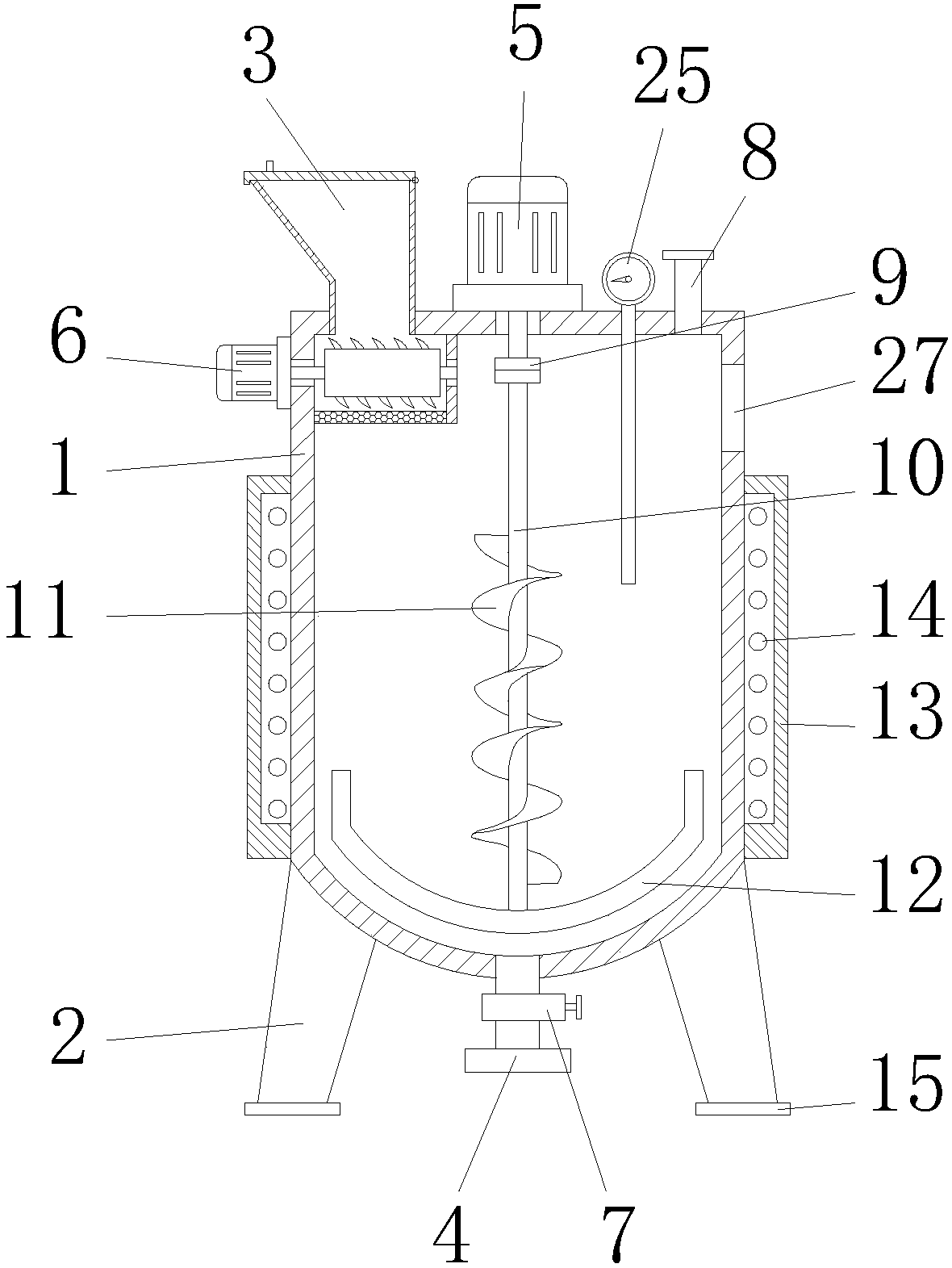
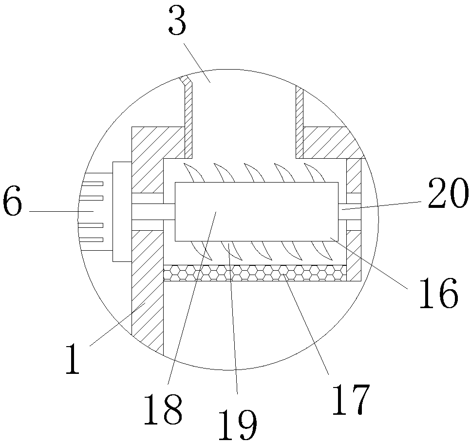
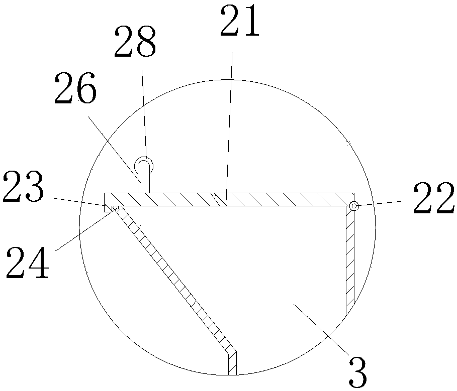
[0018] see Figure 1-3 , the present invention provides a technical solution: a vertical plant fiber reactor, including a tank body 1, legs 2 are installed on the left and right sides of the bottom of the tank body 1, and the legs 2 are used to support the tank body 1. The bottom end of the leg 2 is equipped with a foot pad 15, which has the effect of damping and anti-skid, and the top left side of the tank body 1 is equipped with a feed port 3, and the plant ...


PUM


Abstract

The invention discloses a vertical plant fiber reactor. The vertical plant fiber reactor comprises a tank body, wherein a crushing box is mounted at the top of the left side in the tank body; a screenmesh is mounted at the bottom end of the crushing box; blades are mounted on an outer wall of a cutter roller; a stirring shaft is mounted at the center in the tank body; a spiral blade is mounted onthe outer wall of the stirring shaft. According to the vertical plant fiber reactor disclosed by the invention, the blades, the screen mesh and the spiral blade are matched; the blades are rotated tocrush plant fiber, and the crushed plant fibers fall off from mesh holes of the screen mesh, fall into the bottom end in the tank body and are stirred to react; the plant fibers can be overturned upand down through the rotation of the spiral blade, so that the plant fibers and reaction medicines are uniformly mixed and react better; a valve is switched on and the plant fibers, which are preparedinto pulp after reaction is finished, are discharged out from a discharging hole; the plant fibers are crushed and then are subjected to stirring and reaction; the plant fibers are uniformly stirredand react sufficiently; the pulping quality is good and the utilization requirements of users can be met.

Description

technical field [0001] The invention relates to the technical field of pulping equipment, in particular to a vertical plant fiber reactor. Background technique [0002] When plant fibers are used for pulping, reactors are used in softening, decomposition, bleaching and other steps. Plant fibers need to react with liquid medicine in the reactor. Therefore, the efficiency of the reactor affects the production efficiency of the pulping process. The key factor is that most of the current vertical reactors are reacted by adding drugs in the reactor, so the reaction time is long, and the stirring is consistent during the reaction process, resulting in large power consumption and a large amount of auxiliary agents. It causes high cost of pulping. If the reaction time is reduced, the reaction will be insufficient, the bulk material in the reactor is difficult to fully react, and the pulping quality is poor. In the prior art, such as the invention patent with application number 20162...

Claims


Application Information

Patent Timeline
Patent Type & Authority Applications(China)
IPC IPC(8): B01J19/20B02C18/14
Inventor 刘鹏飞
Owner WUHU LINGMENG E COMMERCE CO LTD
Why Eureka
Try Eureka