Novel ink photocuring device

A kind of ink, a new technology, applied to the surface coating liquid device, pretreatment surface, coating and other directions, can solve the problems affecting the light curing effect, achieve the effect of improving the light curing effect, fast and stable heat dissipation

Inactive Publication Date: 2018-01-09
ZHEJIANG WELLVAST PACKING PRINTING PRODS
View PDF6 Cites 0 Cited by
  • Summary
  • Abstract
  • Description
  • Claims
  • Application Information

AI Technical Summary

Problems solved by technology

[0002] At present, UV spraying is used for paper, PVC, and plastic thin-layer products, and the curing equipment for the ink layer after printing, namely: UV light curing machine, its structure includes a frame, a curing furnace and a conveyor belt, and a workbench is set on the frame , the conveyor belt is set on the workbench of the frame, the curing furnace with built-in UV lamp device is installed on the frame, and is located above the conveyor belt, the bottom of the curing furnace is open, and the top wall of the curing furnace is equipped with an exhaust device, corresponding to The workbench under the conveyor belt at the bottom of the curing furnace has several air suction holes, and the center of the bottom of the workbench is provided with an air exhaust port, which is connected with several air suction holes, and an exhaust fan is arranged on the air exhaust port; When the structured UV light curing machine is performing light curing, the peak value of the UV lamp is 365nm. However, due to the improvement of the ink, such a light curing machine can no longer meet the requirements of light curing. At the same time, when the light curing machine is performing light curing, It will generate a lot of heat, if the heat is not discharged in time, it will affect the light curing effect

Method used


Image

  • Novel ink photocuring device
  • Novel ink photocuring device
  • Novel ink photocuring device

Examples


Embodiment 1

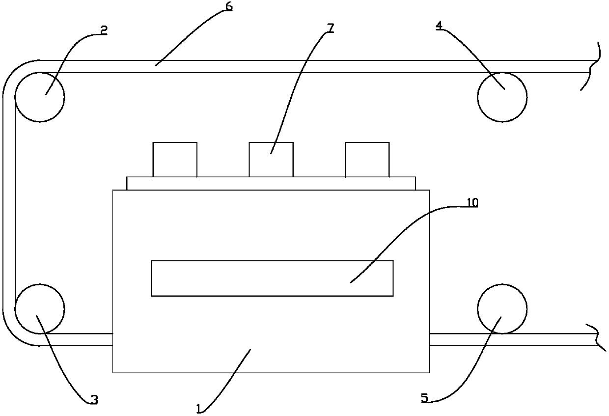
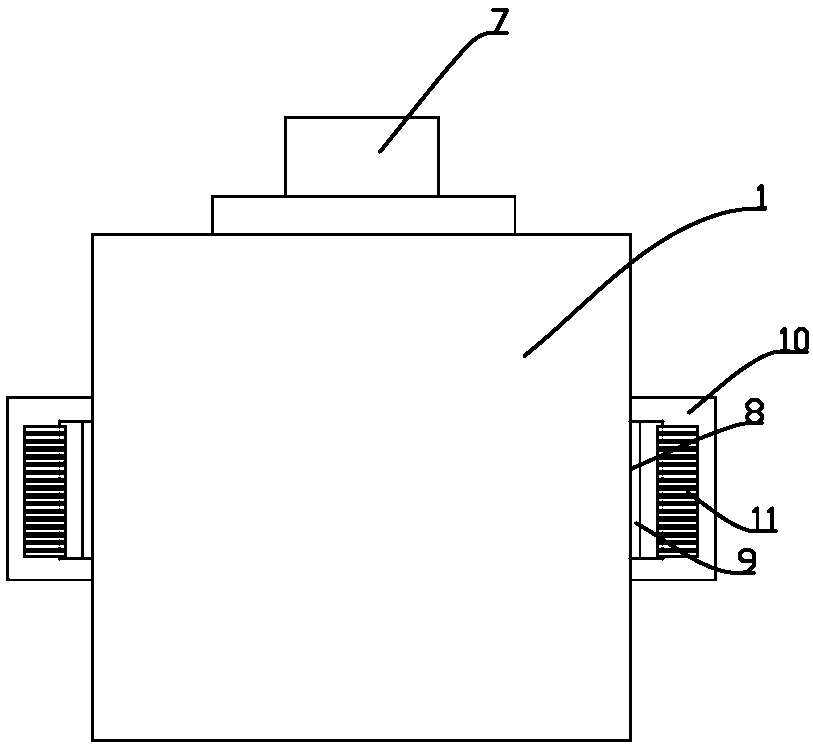
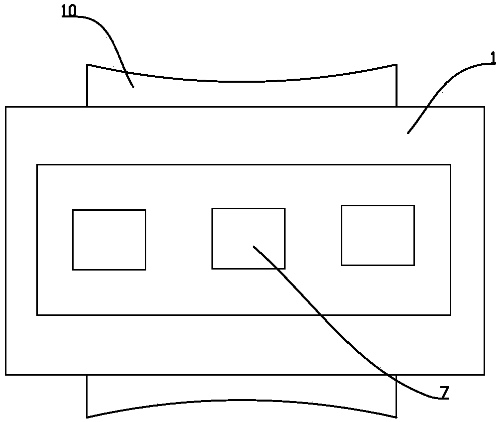
[0016] Such as Figure 1-3 As shown, a new type of ink light-curing device includes a frame and a curing furnace 1 fixed on the frame. The curing furnace 1 is provided with a UV lamp, and the left and right sides of the curing furnace 1 are provided with access The feed port, the frame is provided with an upper left roller 2 and a lower left roller 3 vertically on the left side of the curing furnace 1, and an upper right roller 4 and a lower right roller 5 are arranged vertically on the right side of the curing furnace 1, The upper left roller 2, the lower left roller 3, the upper right roller 4 and the lower right roller 5 are provided with a conveyor belt 6, and the conveyor belt 6 passes through the lower right roller 5, the curing furnace 1, the lower left roller 3, and the upper left roller 2 successively. And the upper right roller 4, the outer top of the curing furnace 1 is provided with a low pressure halogen lamp 7, the upper right roller 4 and the upper left roller 2...


PUM


Abstract

The invention discloses a novel ink photocuring device. The novel ink photocuring device comprises a rack and a curing furnace, wherein an UV lamp pipe is arranged in the curing furnace; a charge portand a discharge port are formed in the left side and the right side of the curing furnace; the rack is provided with an upper left roll and a lower left roll at the left side of the curing furnace inthe vertical direction, and provided with an upper right roll and a lower right roll at the right side of the curing furnace; a conveying belt is arranged on the upper left roll, the lower left roll,the upper right roll and the lower right roll; the conveying belt sequentially passes through the lower right roll, the curing furnace, the lower left roll, the upper left roll and the upper right roll; a low-voltage halogen lamp is arranged at the top of the outer side of the curing furnace; the upper right roll and the upper left roll are both located above the low-voltage halogen lamp in the vertical direction; exhaust ports are formed in the front side and the rear side of the curing furnace separately; an exhaust fan is arranged on each exhaust port; the curing furnace is provided with alight barrier at the outer side of each exhaust port; and each light barrier is in an arc shape with a middle part sunken towards the corresponding exhaust port. According to the novel ink photocuring device disclosed by the invention, secondary photocuring is carried out through the low-voltage halogen lamp above the curing furnace, so that the photocuring effect can be effectively improved; andmeanwhile, rapid and stable heat dissipation is realized by virtue of the exhaust fans.

Description

technical field [0001] The invention relates to a novel ink light-fixing device. Background technique [0002] At present, UV spraying is used for paper, PVC, and plastic thin-layer products, and the curing equipment for the ink layer after printing, namely: UV light curing machine, its structure includes a frame, a curing furnace and a conveyor belt, and a workbench is set on the frame , the conveyor belt is set on the workbench of the frame, the curing furnace with built-in UV lamp device is installed on the frame, and is located above the conveyor belt, the bottom of the curing furnace is open, and the top wall of the curing furnace is equipped with an exhaust device, corresponding to The workbench under the conveyor belt at the bottom of the curing furnace has several air suction holes, and the center of the bottom of the workbench is provided with an air exhaust port, which is connected with several air suction holes, and an exhaust fan is arranged on the air exhaust po...

Claims


Application Information

Patent Timeline
Patent Type & Authority Applications(China)
IPC IPC(8): B05D3/06
Inventor 潘中华金琳肖颖周淑宝李春梅俞忠华
Owner ZHEJIANG WELLVAST PACKING PRINTING PRODS
Why Eureka
Try Eureka