Powder conveying device and application thereof

A powder material conveying and powder material technology is applied in the field of powder material conveying device, which can solve the problems of blanking and large pressure drop, and achieve the effect of preventing material agglomeration, good effect and uniform distribution.

Pending Publication Date: 2018-01-09
KEDA MAS CLEAN ENERGY +1
View PDF10 Cites 4 Cited by
  • Summary
  • Abstract
  • Description
  • Claims
  • Application Information

AI Technical Summary

Problems solved by technology

[0007] Aiming at the problem that the existing powder conveying device is prone to material falling and large pressure drop during operation, the present invention provides a powder conveying device and its application

Method used


Image

  • Powder conveying device and application thereof
  • Powder conveying device and application thereof
  • Powder conveying device and application thereof

Examples


Embodiment 1

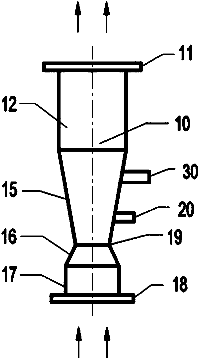
[0052] Such as figure 1 As shown, a powder conveying device includes a lifting pipeline 10 and a feeding pipeline 30, and the lifting pipeline 10 includes an inlet, a lower contraction section 16, an expanding section 15 and an outlet arranged sequentially from bottom to top, and the feeding pipeline 30 is arranged on the expansion section 15 and communicates with the expansion section 15, and the expansion section 15 is also provided with a purge pipeline 20, the purge pipeline 20 is located directly below the feed pipeline 30 and is connected to the expansion section 15. The expansion section 15 communicates with each other.

[0053] Compared with the structure of the powder conveying device in this embodiment, the structure of the existing powder conveying device differs in that: no purge pipe 20 is provided below the feeding pipe 30, and the lifting pipe 10 does not include a constriction structure Therefore, in the existing powder conveying device, after the powder enter...

Embodiment 2

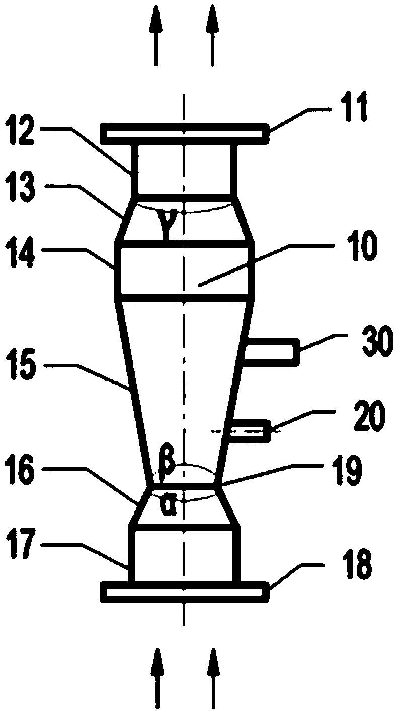
[0056] Such as figure 1 As shown, a powder conveying device, its structure is compared with that of Example 1, the difference is that: the axis of the purging pipe 20 is perpendicular to the outer wall of the expansion section 15, in this arrangement, the purge gas After passing through the purge pipeline 20, the impact force on the material stream is relatively large. In addition, the diameter of the purge pipeline 20 is larger than the diameter of the feed pipeline 30, thereby ensuring that the purge gas can completely blow the material stream. The dispersed material is more easily blown up by the smoke and mixed thoroughly. During specific implementation, it is also possible to adopt a setting method in which the axis of the purging pipe 20 is perpendicular to the axis of the lifting pipe, that is, installing the purging pipe 20 horizontally can also achieve the effect of blowing the material away from the wall.

Embodiment 3

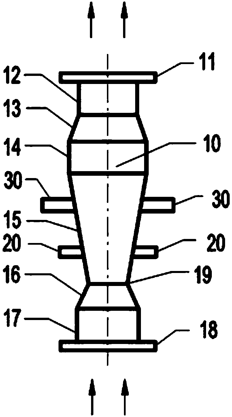
[0058] A kind of powder conveying device, its structure is compared with embodiment 1, and the difference is: the described expansion section 15 is provided with at least one described feeding pipeline 30, the quantity of described purging pipeline 20 and described The number of feed pipes 30 is the same, and the feed pipes 30 and the purge pipes 20 are evenly distributed on the outer periphery of the riser pipe 10, and a blower is arranged directly below each of the feed pipes 30. Sweeping pipeline 20, through the way of evenly arranging multiple feeding pipelines 30 and purge pipeline 20 on the outer periphery of lifting pipeline 10, improves the material feeding mode, makes the material feeding distribution more uniform, prevents the material from agglomerating, and makes the flue gas and material Mix more fully, evenly, during concrete implementation, the quantity of feed pipeline 30 can be two, three, four etc., in the present embodiment the quantity of feed pipeline 30 an...


PUM


Abstract

The invention discloses a powder conveying device and an application thereof, belonging to the field of pneumatic conveying. The powder conveying device comprises a lifting pipeline, a feeding pipeline and a purging pipeline, wherein the lifting pipeline sequentially comprises a lower flange, a lower straight section, a lower contraction section, an expansion section, a middle straight section, anupper contraction section, an upper straight section and an upper flange from bottom to top; the feeding pipeline is arranged on the expansion section and is connected to the lifting pipeline; the axis of the feeding pipeline is perpendicular to the axis of the lifting pipeline; the purging pipeline is arranged on the expansion pipeline and is connected to the lifting pipeline; and the purging pipeline is located right above the feeding pipeline. The powder conveying device solves the technical problems of the powder conveying device in the prior art that a material dropping phenomenon easilyoccurs, and the pressure drop is large. The powder conveying device is capable of fully mixing powder and gas, has small pressure drop in a conveying process, is simple and operates stably and reliably.

Description

technical field [0001] The invention belongs to the field of pneumatic conveying, and more specifically relates to a powder material conveying device and its application. Background technique [0002] The pneumatic conveying device uses the principle of fluidization to convey powder materials in a closed pipeline. The equipment has a simple structure and is easy to operate. It can be conveyed in horizontal, vertical or inclined directions. During the conveying process, the material can also be transported at the same time. Physical operations such as heating, cooling and drying or certain chemical operations. [0003] In the process of dilute-phase pneumatic conveying, in order to convey the powder material vertically upward, it is necessary for the powder material to be evenly distributed in the upward-flowing airflow, and the upward-flowing airflow also needs to have sufficient speed. In order to fully mix the powder material with the gas in the vertical upward pipeline a...

Claims


Application Information

Patent Timeline
Patent Type & Authority Applications(China)
IPC IPC(8): B65G53/52B65G53/40
Inventor 秦亚杰胡振中毕大鹏李金超
Owner KEDA MAS CLEAN ENERGY
Why Eureka
Try Eureka