Cutter wheel with cutting edge grooves
A cutting edge groove and cutter wheel technology, applied in manufacturing tools, glass manufacturing equipment, glass cutting devices, etc., can solve the problems of uneven cutting section, reduced cutting quality, and poor rotation, so as to achieve low cutting resistance and improve cutting. Quality, avoid the effect of poor cutting rotation
- Summary
- Abstract
- Description
- Claims
- Application Information
AI Technical Summary
Problems solved by technology
Method used
Image
Examples
Embodiment 1
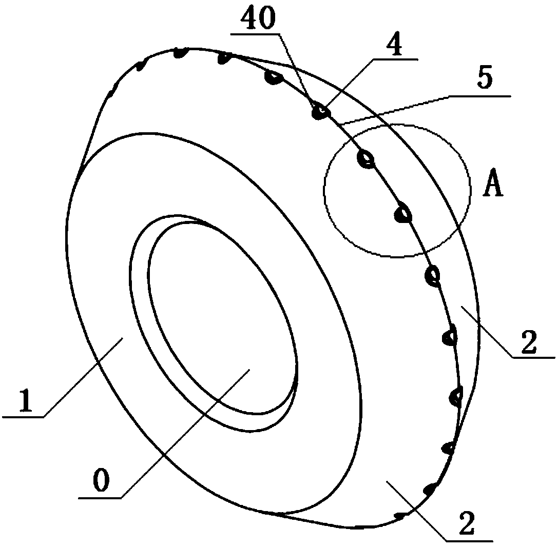
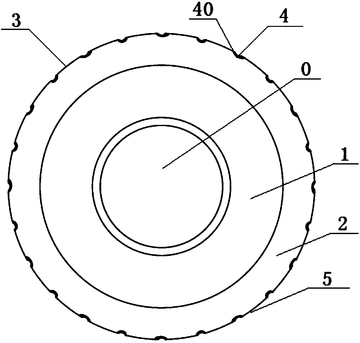
[0031] figure 1 It is a structural schematic diagram of a cutter wheel with an edge groove shown according to a preferred embodiment, figure 2 for figure 1 front view of image 3 for figure 1 side view, such as figure 1 , figure 2 , image 3 As shown, the present embodiment has a cutter wheel with an edge groove, the two sides of the cutter wheel are disc surfaces 1, and the center of the disc surface 1 is provided with a shaft hole 0 for installing the cutter shaft, and the shaft hole 0 is a through hole; the outer circles of the two disc surfaces 1 Extend outward respectively to form a cutter wheel conical surface 2 that connects the two disc surfaces 1 together, and the intersection of the two cutter wheel conical surfaces 2 is a cutting edge 3 . The cutter wheel is provided with concave cutting tooth grooves 4 along the cutting edge 3 , and the cutting tooth grooves 4 are evenly distributed in point and segment along the cutting edge 3 circumferential direction. A...
Embodiment 2
[0039] Such as Figure 5 As shown, this embodiment provides another structure of cutting edge groove 40 as a preference. In this embodiment, the cutting edge groove 40 is spirally arranged on the two cone surfaces 2 around the cutting tooth groove 4 and gradually moves away from the cutting tooth groove 4. The starting point 401 of two adjacent spiral edge grooves 40 is at the two ends of the corresponding cutting tooth groove 4 respectively, the starting point 401 of one spiral edge groove is above the corresponding cutting tooth groove 4, and the other adjacent The starting point 401 of a spiral cutting edge groove is below the corresponding cutting tooth groove 4, and the helical direction of two adjacent cutting edge grooves 40 is opposite, and the end of the cutting edge groove 40 away from the cutting tooth groove 4 is the tail end 402 , the tail ends 402 of two adjacent spiral cutting edge grooves 40 are distributed on the same side of the cutting edge 3 . The tail end...
Embodiment 3
[0042] Such as Figure 6As shown, the present embodiment is further most preferred, providing another structure of the edge groove 40, the starting point 401 of two adjacent spiral edge grooves 40 is distributed at one end of the corresponding cutting tooth groove 4, each edge groove 40 The helical direction is the same, the tail ends 402 of the adjacent two spiral edge grooves are distributed on the same side of the cutting edge 3, and the edge grooves 40 in the adjacent two cutting tooth grooves 4 are at the midpoint between the two cutting tooth grooves 4 The straight line to the center of the cutter wheel is symmetrically arranged as a line of symmetry. This structure reduces the possibility of debris entering the cutter shaft hole and the cutter wheel frame, making the cutting smoother.
PUM
| Property | Measurement | Unit |
|---|---|---|
| diameter | aaaaa | aaaaa |
| diameter | aaaaa | aaaaa |
| thickness | aaaaa | aaaaa |
Abstract
Description
Claims
Application Information
 - R&D
- Intellectual Property
- Life Sciences
- Materials
- Tech Scout
- Unparalleled Data Quality
- Higher Quality Content
- 60% Fewer Hallucinations
Browse by: Latest US Patents, China's latest patents, Technical Efficacy Thesaurus, Application Domain, Technology Topic, Popular Technical Reports.
© 2025 PatSnap. All rights reserved.Legal|Privacy policy|Modern Slavery Act Transparency Statement|Sitemap|About US| Contact US: help@patsnap.com


