Combined type line cutting device

A compound and tangent technology, applied in the field of sewing machines, can solve the problems of not being able to meet the cutting requirements of multiple cutting knives at the same time, the precision cannot be adjusted, and the cutting precision is low, so as to save installation time, have high fault tolerance and improve work efficiency.

Inactive Publication Date: 2018-01-09
潘化英
View PDF0 Cites 0 Cited by
  • Summary
  • Abstract
  • Description
  • Claims
  • Application Information

AI Technical Summary

Problems solved by technology

[0004] The purpose of the present invention is to provide a compound thread cutting device for the deficiencies of the prior art, which solves the problem that the thread cutting device in the prior art cannot meet the cutting requirements of various cutting knives at the same time, and the cutting precision is low, and the precision cannot be adjusted. Low efficiency and single suction duct

Method used


Image

  • Combined type line cutting device
  • Combined type line cutting device
  • Combined type line cutting device

Examples


Embodiment 1

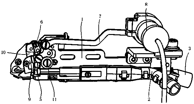
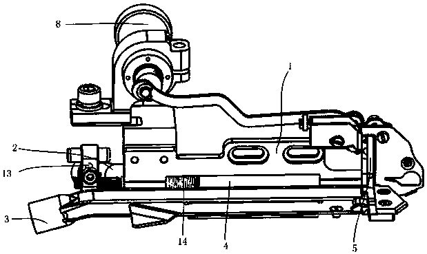
[0023] Embodiment one: if figure 1 , as shown in 2, a composite thread cutting device, including a vertical plate 1, the first air suction channel 2 and the second air suction channel 3 are respectively provided on both sides of the vertical plate 1, and a rotating Shaft 4, one end of the rotating shaft 4 is connected with a first drive motor, and the other end is connected with a chopping knife 5; one side of the vertical plate 1 is provided with a transmission rod 7, and one end of the transmission rod 7 is connected with a second drive The other end of the motor 8 is hinged with a movable air suction knife 9, the movable air suction knife 9 is hinged on the vertical plate 1, and the front end of the vertical plate 1 is also fixedly provided with a fixed air suction knife that cooperates with the movable air suction knife 9. Wind Knife10.

Embodiment 2

[0024] Embodiment two: if figure 1 , as shown in 2, a composite thread cutting device, including a vertical plate 1, the first air suction channel 2 and the second air suction channel 3 are respectively provided on both sides of the vertical plate 1, and a rotating Shaft 4, one end of the rotating shaft 4 is connected with the first drive motor, and the other end is connected with the chopping knife 5, and the vertical plate 1 above the chopping knife 5 is provided with a lattice block 6; one side of the vertical plate 1 A transmission rod 7 is provided, one end of the transmission rod 7 is connected with a second driving motor 8, and the other end is hinged with a movable air suction knife 9, and the movable air suction knife 9 is hinged on the vertical plate 1, and the vertical air suction knife 9 is hinged. The front end of the plate 1 is also fixedly provided with a fixed air suction knife 10 cooperating with the movable air suction knife 9 .

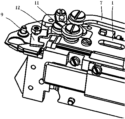
[0025] image 3 As shown, ...


PUM


Abstract

The invention discloses a composite thread cutting device, which comprises a vertical plate, a first air suction channel and a second air suction channel are respectively arranged on both sides of the vertical plate, a rotating shaft is arranged under the vertical plate, and the rotating shaft One end is connected with the first driving motor, and the other end is connected with the chopping knife, and the vertical plate above the said chopping knife is provided with a grid block; one side of the vertical plate is provided with a transmission rod, and one end of the transmission rod is connected with a The second drive motor is hinged with a movable air suction knife at the other end, the movable air suction knife is hinged on the vertical plate, and the front end of the vertical plate is also fixedly provided with a fixed air suction knife matched with the movable air suction knife. It can meet the cutting requirements of various cutting knives at the same time, with high cutting precision and can meet the requirements of multiple blade suction at the same time.

Description

technical field [0001] The invention relates to the technical field of sewing machines, in particular to a compound thread cutting device. Background technique [0002] Existing computerized overlock sewing machines all have thread cutter device, and this thread cutter device is positioned at the rear of needle plate. The device drives the thread cutter through the electromagnet to cut off the thread braids at the front end of the sewing material and the thread braids at the rear end of the sewing material. When the operator feeds the cloth straight forward, it can well cut off the front and back braids of the sewing material. However, due to the operating habits of the sewing worker, the sewing material is pulled back when the rear end of the sewing material has not passed the thread cutter when feeding, and when the cloth is fed in an oblique direction, it is easy for the thread cutter to fail to cut the rear end of the sewing material. In this case, the work efficiency ...

Claims


Application Information

Patent Timeline
Patent Type & Authority Applications(China)
IPC IPC(8): D05B65/06D05B81/00
Inventor 潘怡洁
Owner 潘化英
Why Eureka
Try Eureka