
Eureka
For R&D, Eureka makes reading and utilizing patents & technical documents easy.
Eureka AIR
Designed for self-driven R&D workflows. Generate viable solutions, solve complex R&D challenges, empower your innovation with AI.

Eureka Materials
Designed for material experts only. Revolutionize your material R&D, from search, analyze, to developing new materials.

TechResearch
Generate reliable direction feasibility study reports for your R&D in just a few steps.

TechSeek
Discover and master advanced knowledge NOW. Basics, ideas, possibilities, all at once.

TechMind
As an expert in R&D Theories, TechMind can generates customized viable solutions instantly.

TechRisk
Analyze your overall solution with one click, know your potential R&D risks in advance.

TechMonitor
Get weekly tech updates, stay abreast of the latest tech innovations and key insights.
Drainage system capable of achieving water collection and slow leakage successively
A drainage system and water collection technology, which is applied in the sponge city, municipal engineering, and urban drainage fields, can solve the problems of poor durability and low strength of permeable pavement, and achieve the effect of reducing urban waterlogging and facilitating maintenance
- Summary
- Abstract
- Description
- Claims
- Application Information
AI Technical Summary
Problems solved by technology
Method used
Image

Examples
Embodiment 1
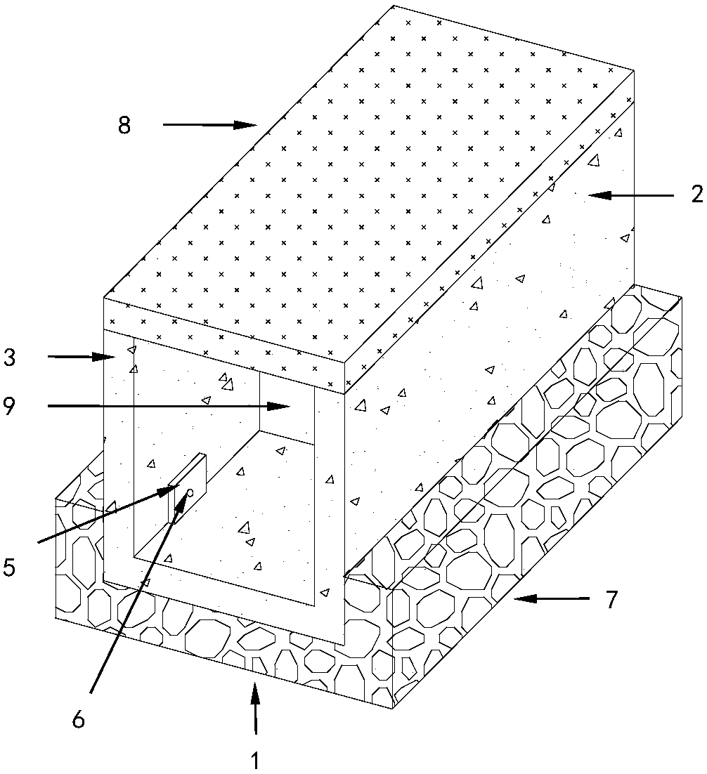
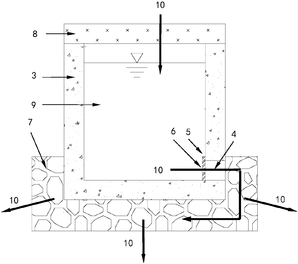
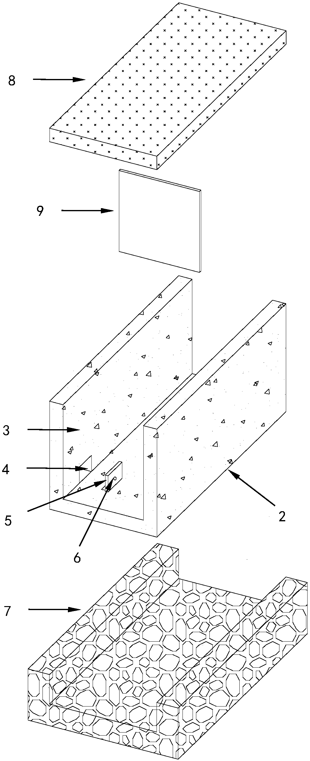
[0030] Such as Figure 1 to Figure 5 As shown, an example of the first water collection and then slow leakage drainage system described in the present invention is a water collection first and then slow leakage water system 1 for underground, including a water collection structure 2, a water leakage hole 6, a gravel layer 7, a water permeable Reinforced roof 8 and partition 9, the specific structure is: the wall of the water collection structure 2 is provided with a number of leakage holes 6, the outer side and bottom of the water collection structure 2 are provided with gravel layers 7, and the top of the water collection structure 2 is provided with The water-permeable and reinforced top cover 8 is provided with a partition 9 inside the water collecting structure 2 .
[0031] This embodiment can be used in parking lots, sidewalks, car dividers and other underground facilities.
[0032] The permeable and reinforced top cover 8 of this embodiment is used as the upper surface ...
Embodiment 2
[0034] Such as Image 6 As shown, the present embodiment is used on the ground for the first water collection and then slow leakage system, and utilizes the first water collection and then slow leakage drainage system to intercept roof rainwater for irrigation. The rainwater first enters the drainage system 1 through the rainwater pipe to first collect water and then leak slowly, and then injects into the green belt or other permeable surfaces through the leak hole 6 to infiltrate to replenish groundwater, prolong the irrigation effect of rainwater, and reduce the use of other irrigation equipment.
Embodiment 3
[0036]This embodiment is another example of the water-collecting first and then slow-leakage drainage system described in the present invention. It uses impermeable concrete slabs to make a concrete box without a roof with an inner diameter of 1m×0.5m×0.5m, and the concrete slabs are connected. Seal with glass glue. The short-side sidewall simulates a partition 9, and a water leakage hole 6 with an aperture of 1.5mm is opened on the long-side sidewall of the concrete box at a distance of 2.5cm from the bottom. The inside of the side wall of the concrete box is pasted with a scale with the same height as the box for real-time observation of water leakage and water level of the water tank. Place the concrete box inside a pre-excavated pit, that is, the slope of the concrete box is 0. The soil in the lower layer of the pit is silty clay with a permeability rate of 1.5×10- 7 m / s, the porosity is 18%, the saturation is 50%, and the bottom of the concrete box and the outside of th...
PUM
 Abstract
Description
Claims
Application Information
 - R&D Engineer
- R&D Manager
- IP Professional
- Industry Leading Data Capabilities
- Powerful AI technology
- Patent DNA Extraction
Browse by: Latest US Patents, China's latest patents, Technical Efficacy Thesaurus, Application Domain, Technology Topic, Popular Technical Reports.
© 2024 PatSnap. All rights reserved.Legal|Privacy policy|Modern Slavery Act Transparency Statement|Sitemap|About US| Contact US: help@patsnap.com