
Gypsum line drying device

A drying device and gypsum line technology, applied in drying, drying machine, heating device and other directions, can solve the problems of low production efficiency, high production cost, long production time, etc., and achieve cost saving, production site saving, and saving The effect of production costs

Pending Publication Date: 2018-01-09
峨眉山市万晟新材料科技有限公司
View PDF0 Cites 9 Cited by
  • Summary
  • Abstract
  • Description
  • Claims
  • Application Information

AI Technical Summary

Problems solved by technology

[0004] Based on the above technical problems, the present invention provides a gypsum line drying device, thereby solving the technical problems of waste of space, long production time, time-consuming, laborious, low production efficiency, and high production cost in the existing gypsum line drying process

Method used


Image

  • Gypsum line drying device
  • Gypsum line drying device
  • Gypsum line drying device

Examples


Embodiment 1

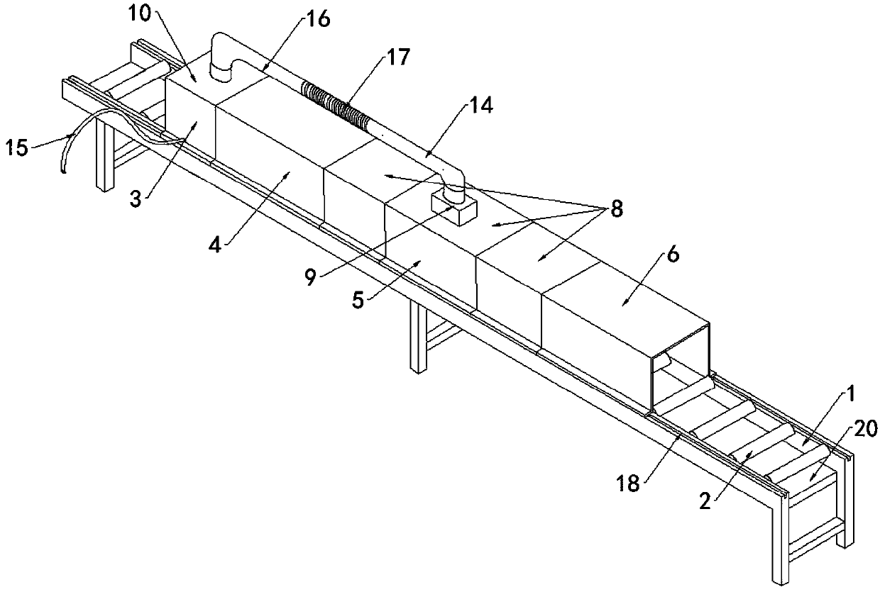
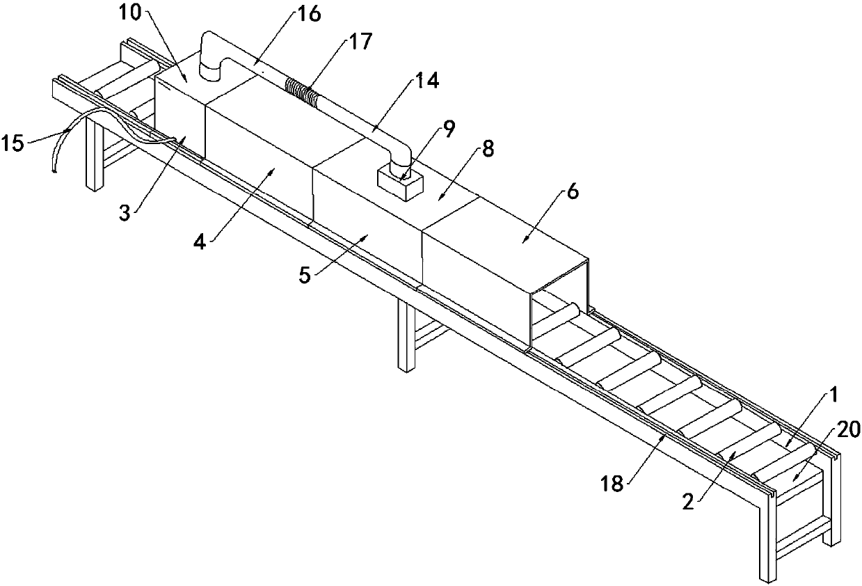
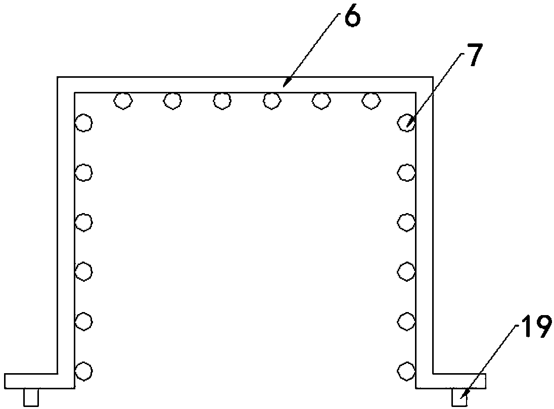
[0034] Such as figure 2 As shown, a gypsum line drying device includes a support frame 1 and a roller 2 arranged in the middle of the support frame 1. The support frame 1 is sequentially provided with a preheating device 3, a primary drying device 4, and a dehumidification device. 5 and the secondary drying device 6, the preheating device 3, the primary drying device 4, the dehumidification device 5 and the secondary drying device 6 are all hollow inside and open at the bottom; the primary drying device 4 is microwave A heater, a plurality of heating pipes 7 are evenly distributed inside the secondary drying device 6;

[0035] The dehumidification device 5 includes a housing a8, the upper part of the housing a8 is provided with an exhaust fan 9, the preheating device 3 includes a housing b10, the housing b10 includes an outer plate 11 and an inner plate 12, and the outer plate 11 and the inner plate 12 There is a gap between them, and a closed heat exchange chamber 13 is forme...

Embodiment 2

[0037] This embodiment is further optimized based on Embodiment 1. The housing a8 in the dehumidification device 5 is set to a plurality; The pipe 17 is screwed to the two connecting pipes 16, and the length of the dehumidification device 5 can be changed by adjusting the number of shells a8 according to the moisture in the gypsum line due to weather or ingredients, so that the water vapor in the drying process All discharge; adjusting pipe 17 is threadedly connected with connecting pipe 16, and the length of pipeline 14 can be adjusted according to the length of dehumidifier 5, so that pipeline 14 can adapt to the change of dehumidifier 5 length.

Embodiment 3

[0039] This embodiment is further optimized based on Embodiment 2, and the joints of the plurality of casings a8 are provided with sealing rings, which can improve the sealing performance of the dehumidification device 5 .


PUM


Abstract

The invention relates to the technical field of gypsum line production equipment, and discloses a gypsum line drying device. The gypsum line drying device comprises a supporting frame and rollers; a pre-heating device, a primary drying device, a dehumidifying device and a secondary drying device are sequentially arranged on the supporting frame; the primary drying device is a microwave heater; a plurality of heating pipes are evenly distributed in the secondary drying device; an exhaust fan is arranged on the upper portion of the dehumidifying device; and a pipeline is arranged between the dehumidifying device and the exhaust fan. By means of the gypsum line drying device, gypsum lines can be fast dried, and therefore it is not needed to move the gypsum lines to an airing field for naturalairing, the production site is saved, the work efficiency is improved, and the production cost is saved; the microwave heater is adopted as the primary drying device, the interiors of the gypsum lines can be heated by microwave heating, heating is uniform, the secondary drying device can fast heat the gypsum lines, the drying efficiency is improved, and therefore the production time is shortened,and the production cost is reduced; and waste heat can be utilized to pre-heat the gypsum lines, and energy conservation and environmental protection are achieved.

Description

technical field [0001] The invention relates to the technical field of gypsum line production equipment, in particular to a gypsum line drying device. Background technique [0002] Gypsum lines made of gypsum and gypsum powder are widely used in the field of architectural decoration. They have the advantages of environmental protection, energy saving, fire prevention, light weight and moderate strength. They have become a new type of building decoration material strongly advocated by the state. [0003] The gypsum lines need to be dried during the production process. In the traditional production process, the formed gypsum lines are placed on a drying rack and allowed to dry naturally. This method requires at least 3 people to remove them from the machine. Put the gypsum lines to the drying yard, and it will take a week to dry at a temperature of 40°C. During the drying process, some gypsum lines will be damaged, which will cause a lot of cost backlog and waste of space for ...

Claims


Application Information

Patent Timeline
Patent Type & Authority Applications(China)
IPC IPC(8): F26B15/12F26B23/04F26B23/08F26B25/00
CPCY02P70/10
Inventor 万志平伍明
Owner 峨眉山市万晟新材料科技有限公司
Learn More