Hydraulic cylinder detection device for lathe
A detection device and hydraulic cylinder technology, applied in the field of hydraulic equipment, can solve the problems of easy damage and high cost
- Summary
- Abstract
- Description
- Claims
- Application Information
AI Technical Summary
Problems solved by technology
Method used
Image
Examples
Embodiment Construction
[0013] The present invention will be described in further detail below by means of specific embodiments:
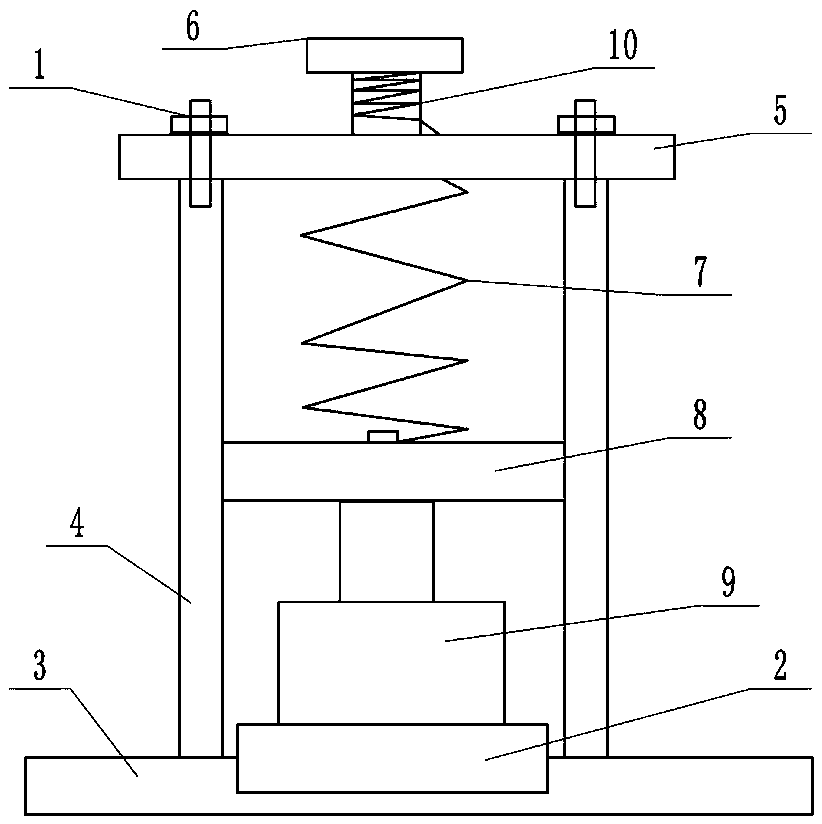
[0014] The reference signs in the drawings of the description include: bolt 1, groove 2, base 3, travel box 4, cover plate 5, rectangular block 6, spring 7, horizontal plate 8, hydraulic cylinder 9, screw rod 10.
[0015] The embodiment is basically as figure 1 Shown:
[0016] The hydraulic cylinder detection device for a lathe of this embodiment comprises a base 3, which is provided with a groove 2 for placing the hydraulic cylinder 9; the base 3 is provided with a stroke box 4, and the inner wall of the stroke box 4 is provided with a chute, and the slide A horizontal plate 8 is slidably connected to the groove, and the side wall of the stroke box 4 is provided with a scale. A hydraulic cylinder 9 to be detected is placed under the horizontal plate 8. The output end of the hydraulic cylinder 9 is offset against the bottom surface of the horizontal plate 8, and the top ...
PUM
 Abstract
Description
Claims
Application Information
 - R&D
- Intellectual Property
- Life Sciences
- Materials
- Tech Scout
- Unparalleled Data Quality
- Higher Quality Content
- 60% Fewer Hallucinations
Browse by: Latest US Patents, China's latest patents, Technical Efficacy Thesaurus, Application Domain, Technology Topic, Popular Technical Reports.
© 2025 PatSnap. All rights reserved.Legal|Privacy policy|Modern Slavery Act Transparency Statement|Sitemap|About US| Contact US: help@patsnap.com

