
Omnibearing image acquisition composite lens

An all-round technology for image acquisition, applied in optics, viewfinders, instruments, etc., which can solve problems such as high cost, complex structure, and inability to use virtual images as judicial evidence.

Inactive Publication Date: 2018-01-09
严平
View PDF7 Cites 1 Cited by
  • Summary
  • Abstract
  • Description
  • Claims
  • Application Information

AI Technical Summary

Problems solved by technology

[0003] It can be seen that among the above two typical panorama image acquisition technologies, although the former has a simple structure, because it performs image acquisition through the reflection of the curved mirror directly above the lens, it is only the surrounding scene within the reflection range of the curved mirror, while In the true sense, it can cover the entire spherical surface for all-round viewing; the latter requires complex calculations to obtain virtual images, which not only require the addition of image processing devices, resulting in complex structures and high costs, but also the virtual images after data processing cannot be used as judicial evidence. Possibly, such as vehicle insurance claims, accident monitoring and other occasions that require judicial evidence collection, you may encounter trouble

Method used


Image

  • Omnibearing image acquisition composite lens
  • Omnibearing image acquisition composite lens
  • Omnibearing image acquisition composite lens

Examples


Embodiment Construction

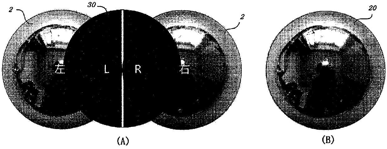
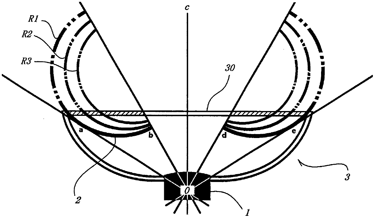
[0023] As the core technology and structural principle, figure 1 The layout of the convex reflector and the principle of framing in the compound lens structure for omnidirectional image acquisition of the present invention are shown. Based on the basic principles of geometric optics, the convex mirror 2 usually has a circular projection shape with high efficiency. Unless otherwise specified, the mirror surface structures described later in the present invention all have a circular projection shape.

[0024] see figure 1 (A), the two adjacent convex reflectors 2 marked "left" and "right" in the figure, even if the two parts of the adjacent mirrors in the area covered by the shaded parts "L" and "R" in the figure are symmetrically cut off , so that it has a mirror gap 30, it can still obtain the field of view equivalent to a single complete convex mirror, such as figure 1 The technical effect of the equivalent convex mirror 20 shown in (B). The reflector gap 30 is beneficial ...


PUM


Abstract

An omnibearing image acquisition composite lens comprises a shooting lens; the shooting lens has a preset optics visual angle so as to determine a front visual field; two convex surface reflectors inthe same shape are symmetrically arranged in the front visual field scope of the shooting lens, take the shooting lens optical axis c as the symmetrical center, and used for reflecting scenes surrounding the shooting lens and partial the scenes behind the shooting lens into the shooting lens; a reflector gap is arranged between the symmetrically arranged convex surface reflectors, thus allowing the shooting lens to directly obtain the scenes in certain scope right in front of the shooting lens; therefore, the shooting lens can directly shoot images in a front preset visual field scope, and theconvex surface reflectors can shoot the visual field scenes surrounding the shooting lens and partial the scenes behind the shooting lens, thus approaching a whole spherical surface visual field coverage effect.

Description

technical field [0001] The invention relates to an optical lens structure, in particular to a composite lens for omnidirectional image collection. Background technique [0002] Present typical panorama lens usually expands the field of view by means of a curved mirror, and uses an ordinary camera to obtain the field of view of the surrounding environment. The improvement to the above-mentioned curved reflector reduces the complexity and difficulty of system design and obtains wider applicability. With the development of image processing electronic technology (especially computer graphics), the technology of obtaining normal perspective panoramic effect by superimposing and correcting the collected images is also disclosed. For example, Chinese patent application publication CN104835117A describes a spherical panorama in an overlapping manner. The image generation method includes pixel fusion based on the principle of image fusion, numerical calculation for the overlapping a...

Claims


Application Information

Patent Timeline
IPC IPC(8): G03B13/06G03B17/17
CPCG03B17/17G03B37/00G02B17/0804G02B13/06
Inventor 严平
Owner 严平
Learn More