High-gain novel orthographic projection ultra short-focus screen

A front projection, high gain technology, used in optics, instruments, projection devices, etc., to achieve the effect of reducing concentration, reducing cost, and improving gain

Pending Publication Date: 2018-01-09
成都恒坤光显材料科技有限公司
View PDF7 Cites 22 Cited by
  • Summary
  • Abstract
  • Description
  • Claims
  • Application Information

AI Technical Summary

Problems solved by technology

However, it is difficult for existing projection screens to effectively increase the gain and brightness of the screen while ensurin

Method used


Image

  • High-gain novel orthographic projection ultra short-focus screen
  • High-gain novel orthographic projection ultra short-focus screen
  • High-gain novel orthographic projection ultra short-focus screen

Examples


Embodiment 1

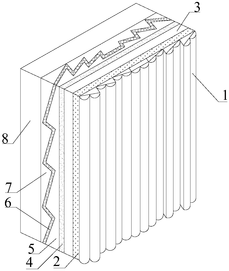
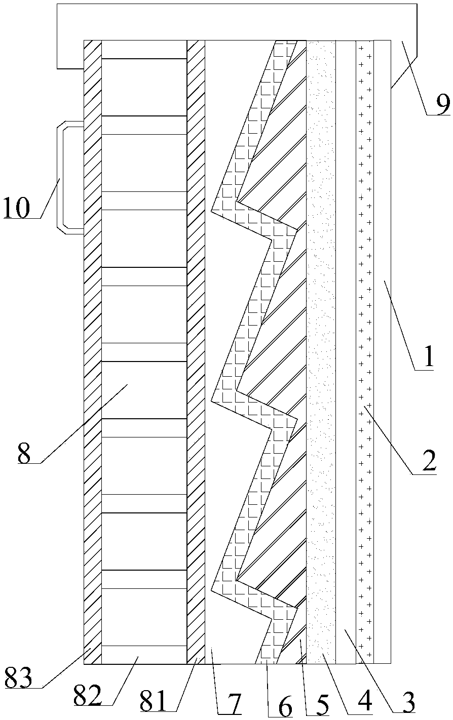
[0039] Such as Figure 1-2 As shown, a new type of high-gain front projection ultra-short focus screen, including Fresnel cylindrical layer 1, colored layer 2, base layer 3, scattering layer 4, circular Fresnel lens layer 5 and reflective layer bonded in sequence 6. The Fresnel cylindrical surface layer 1 includes several Fresnel lens cylindrical tooth units 11 arranged vertically, all the cylindrical tooth units 11 are connected to each other and arranged in an array, and each of the cylindrical At least one cylindrical lens unit 12 arranged vertically is arranged on the working surface of the tooth unit 11 .

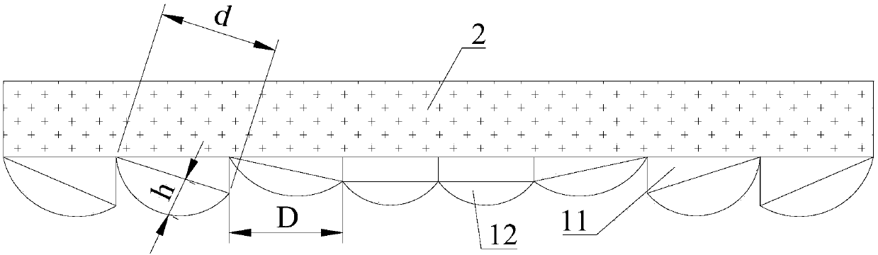
[0040] Such as image 3 As shown, the cylindrical width D of each cylindrical tooth unit 11 is 0.1mm-0.4mm, and a vertically arranged cylindrical lens unit 12 is arranged on the working surface of each cylindrical tooth unit 11 , the cylindrical lens unit 12 is an arc cylindrical structure, the ratio of the cylindrical depth h of all the cylindrical lens units 12 to ...

Embodiment 2

[0046] Such as Figure 4 As shown, the difference between this embodiment and Embodiment 1 is that two cylindrical lens units 12 arranged vertically are arranged on the working surface of each columnar tooth unit 11, and the cylindrical lens units 12 are In the arc cylindrical structure, the ratio of the cylinder depth h to the cylinder width d of all the cylinder lens units 12 is 0.1-2. By arranging two cylindrical lens units 12, the refractive index of the outgoing light can be increased, further expanding the horizontal viewing angle within a certain range.

Embodiment 3

[0048] Such as Figure 5 As shown, the difference between this embodiment and Embodiment 1 is that three cylindrical lens units 12 arranged vertically are arranged on the working surface of each columnar tooth unit 11, and the cylindrical lens units 12 are circular An arc column structure or a triangular prism structure, all the arc columns and the triangular prisms are connected to each other and arranged in an array, and the ratio of the cylinder depth h to the cylinder width d of all the cylinder lens units 12 is 0.1 -2. By arranging three cylindrical lens units 12, the refractive index of the outgoing light can be increased, further expanding the horizontal viewing angle within a certain range.


PUM

PropertyMeasurementUnit
Surface hardnessaaaaaaaaaa

Abstract

The invention discloses a high-gain novel orthographic projection ultra short-focus screen. The high-gain novel orthographic projection ultra short-focus screen comprises a Fresnel cylindrical layer,a pigmented layer, a base layer, a scattering layer, a circular Fresnel lens layer and a reflecting layer which are sequentially bonded. The Fresnel cylindrical layer comprises several Fresnel lens cylindrical tooth units which are vertically arranged, all the cylindrical tooth units are connected with one another and are sequentially arranged in an array, and the work surface of each cylindricaltooth unit is provided with at least one cylindrical lens unit which is vertically arranged. The Fresnel cylindrical layer combines cylindrical Fresnel lenses and cylindrical lenses, and therefore theFresnel cylindrical layer has advantages of the cylindrical Fresnel lenses and the cylindrical lenses, and can help the circular Fresnel lens on the back of the screen to control light emitted by a projector in the horizontal direction to some extent; at the same time, by employing the cylindrical lenses, the visual angle in the horizontal direction can be increased, on the premise that the horizontal visual angle keeps constant, the concentration of scattering diluents in the screen scattering layer can be reduced, the upper and lower visual angle of the screen can be reduced, and the gain is increased.

Description

technical field [0001] The invention relates to a projection screen, in particular to a novel front projection ultra-short focus screen with high gain. Background technique [0002] Most of the existing ultra-short-throw front projection screens are imaged by scattering, such as white plastic screens, which have no selectivity to ambient light, resulting in a great impact of ambient light on the projection effect. When the ambient light is brighter, the projection display The lower the contrast, the poorer the display. [0003] In order to overcome the above defects, people use a Fresnel lens plus a scattering agent on the projection screen to achieve. The Fresnel lens can eliminate the influence of ambient light and improve the contrast of the screen, and the scattering agent provides the viewing angle. However, due to its own principle, the viewing angle of the screen is consistent with the horizontal direction and the up and down direction. In practical applications, peo...

Claims


Application Information

Patent Timeline
IPC IPC(8): G03B21/602
Inventor 周礼书霍永峰
Owner 成都恒坤光显材料科技有限公司
Why Eureka
Try Eureka