Machining trajectory planning method of variable tool machining path with equal residual height

A technology of equal residual height and machining trajectory, applied in the direction of digital control, electrical program control, etc., can solve problems such as the discussion of the problem of jointing tool marks, and achieve the effects of ensuring processing quality, reducing jointing tool marks, and high-precision and efficient machining

Active Publication Date: 2019-10-11
DALIAN UNIV OF TECH
View PDF5 Cites 0 Cited by
  • Summary
  • Abstract
  • Description
  • Claims
  • Application Information

AI Technical Summary

Problems solved by technology

However, this method only considers the machining trajectory planning of each machining area, and does not discuss the problem of connecting tool marks at the border of adjacent machining areas, which has certain limitations

Method used


Image

  • Machining trajectory planning method of variable tool machining path with equal residual height
  • Machining trajectory planning method of variable tool machining path with equal residual height
  • Machining trajectory planning method of variable tool machining path with equal residual height

Examples


Embodiment Construction

[0093] The specific embodiments of the present invention will be described in detail with reference to the technical solutions and the accompanying drawings.

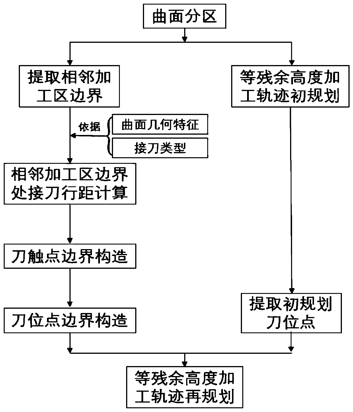
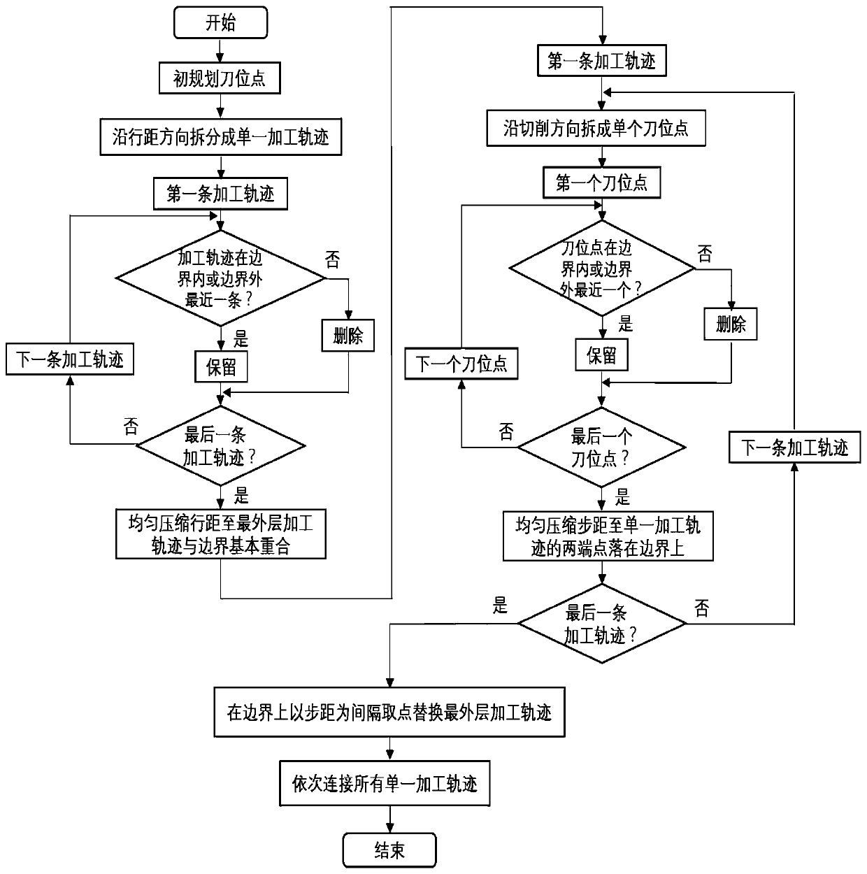
[0094] When the surface is divided into different cutting tools, the initial planning of the processing path is carried out separately for each processing area, resulting in obvious tool marks at the boundary of adjacent processing areas, which seriously affects the surface processing quality. In view of this situation, in order to reduce the tool marks at the boundary of the adjacent processing area, a method for planning the machining path of the surface area with equal residual height and variable tool machining was invented. The overall process is shown in the appendix. figure 1 shown.

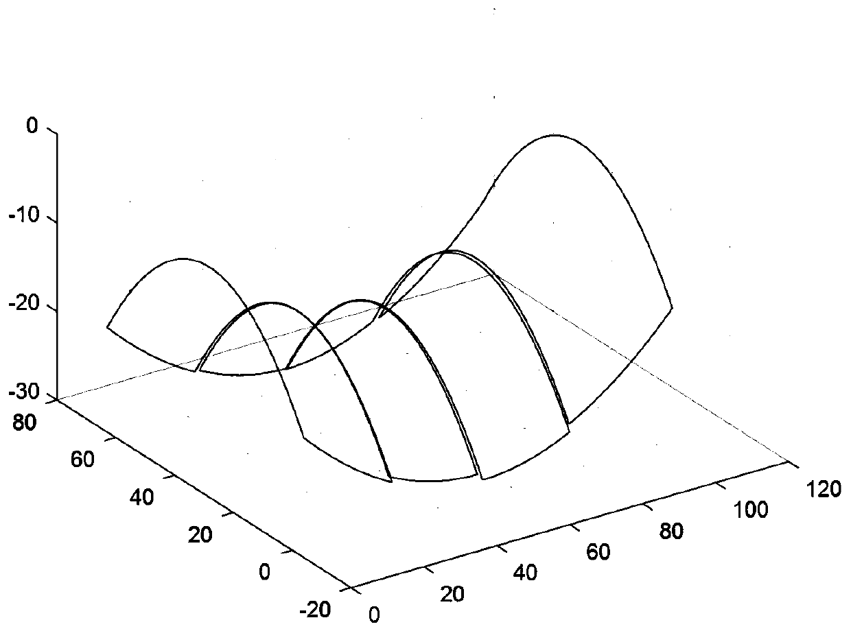
[0095] Taking the saddle surface milling with different milling cutters as an example, with the help of UG software and MATLAB software, the implementation process of the present invention is described in detail.

[0096] First, us...


PUM


Abstract

The invention discloses a track planning method of turning curved surface zone having equal scallop-height into a cutter processing, which belongs to the technical field of highly-precise and highly-efficient milling and processing of complicated curved surface parts. The track planning method of turning curved surface zone having equal scallop-height into a cutter processing comprises the steps of conducting zone partitioning on the curved surface based on the geometric features and processing requirement of the curved surface; determining the boundary of adjacent processing zones; conductingthe initial plan of equal scallop-height processing track on different processing zones. Through analyzing the geometric features of boundary, the geodesic radius of curvature and the cutter space along the space direction can be calculated, and the cutter contact point and cutter position point corresponding to any points on the boundary of adjacent processing zones can be resolved. The cutter position points form the cutter point boundary through interpolation and fitting. The invention is advantageous in that planning can be conducted with the cutter position point being the constraint, and it can be guaranteed that the cutter position point falls in the cutter position point boundary and on the boundary; the cutter position point can be adjusted, so that the error brought by planningcan be homogenized; the method is suitable for turning the complicated curved surface into cutter processing, and gear mark can be reduced, and processing quality can be improved.

Description

technical field [0001] The invention belongs to the technical field of high-precision and high-efficiency milling processing of complex curved surface parts, and relates to a method for planning a machining trajectory of a curved surface partition and variable tool with equal residual height. Background technique [0002] Complex surface parts are widely used in various fields such as aerospace, automobiles, ships, etc. Today, complex surface modeling technology has gradually matured, but how to achieve high-precision and high-efficiency machining of complex surface parts is still a research hotspot and difficulty. As the surface structure becomes more and more complex, the conventional machining method using unified process parameters for global machining is less suitable, especially for complex surface parts with local geometric abrupt changes. In order to meet the machining accuracy requirements of local geometrically rapidly changing complex surfaces, improve machining e...

Claims


Application Information

Patent Timeline
Patent Type & Authority Patents(China)
IPC IPC(8): G05B19/19
Inventor 马建伟赵孝轩贾振元秦逢泽张宁
Owner DALIAN UNIV OF TECH
Why Eureka
Try Eureka